Display panel and display device with same
A display panel and display layer technology, applied in the direction of electrical components, electrical solid devices, circuits, etc., can solve the problems that affect the overall aesthetics of the display device, so as to improve the overall appearance effect and alleviate the visible effect
- Summary
- Abstract
- Description
- Claims
- Application Information
AI Technical Summary
Problems solved by technology
Method used
Image
Examples
Embodiment 1
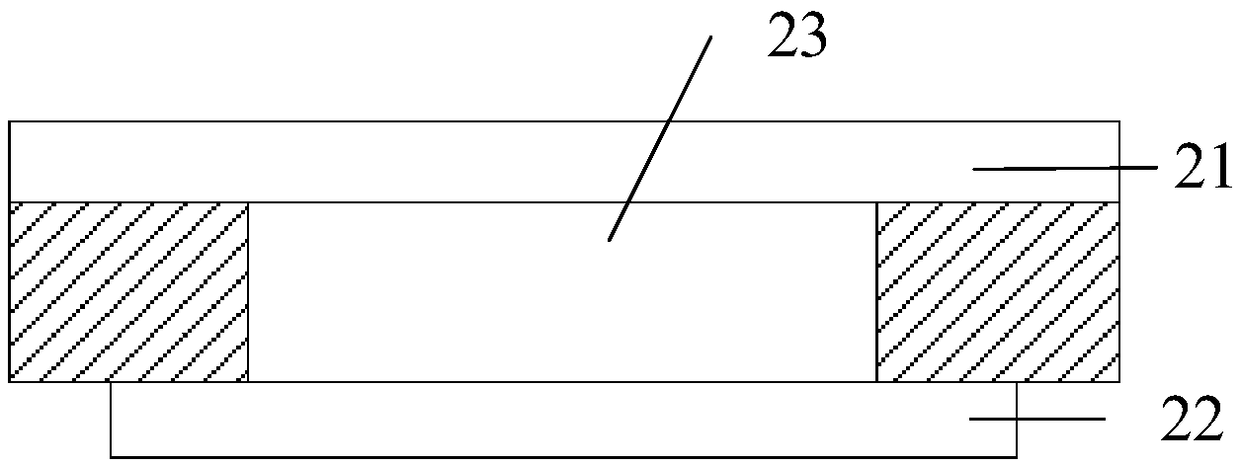
[0028] This application provides a display panel, such as figure 2 shown, including:
[0029] display layer 21;
[0030] A photosensitive module 22 located inside the display layer 21;
[0031] An optical barrier layer 23 disposed between the display layer 21 and the photosensitive module 22;
[0032] The optical blocking layer 23 is used to reduce the intensity of light emitted from the display layer 21 to the photosensitive module 22 and / or the intensity of light reflected by the photosensitive module 22 to the display layer 21 .
[0033] That is to say, the optical blocking layer 23 can be used to reduce the intensity of the light emitted from the display layer 21 to the photosensitive module 22. When the light is transmitted from the display layer 21 to the photosensitive module 22, it will be affected by the optical blocking layer 23. strong weakening, so that the light reflected by the photosensitive module 22 back to the outside is weaker, which can reduce the visib...
Embodiment 2
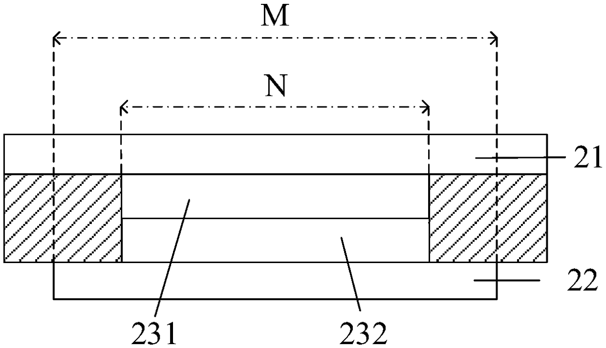
[0039] Based on the scheme of the above-mentioned embodiment, such as image 3 As shown, the embodiment of the present application also provides a better display panel, the optical barrier layer includes at least one optical film (optical film 231 and optical film 232 in the figure), and the orthographic projection of the optical film on the plane where the display layer 21 is located N is located within the range of the orthographic projection M of the photosensitive module 22 on the plane where the display layer 21 is located.
[0040] exist image 3The optical barrier layer shown in includes a first optical film 231 close to the display layer and a second optical film 232 close to the photosensitive module. The materials and structures of these two optical films can be the same or different. According to actual production requirements, the optical The blocking layer may also include more or less optical films, which are used to reduce the intensity of light emitted from th...
Embodiment 3
[0083] For the above-mentioned problems in the prior art, the present application provides a display device including any display panel in the above-mentioned embodiments.
[0084] In addition, the above display device may also include a frame for maintaining the shape of the display panel, and related driving components for driving the display layer and the photosensitive module, and the driving components may include electronic modules such as chips.
[0085] In the present application, an optical blocking layer is set between the display layer and the photosensitive module to reduce the intensity of light emitted from the display layer to the photosensitive module and / or the intensity of light reflected from the photosensitive module to the display layer, so that the reflection of each area of the display panel The light is basically consistent, which can reduce the visibility of the photosensitive module under the display layer, thereby alleviating the visible problem of ...
PUM
 Abstract
Description
Claims
Application Information
 - R&D
- Intellectual Property
- Life Sciences
- Materials
- Tech Scout
- Unparalleled Data Quality
- Higher Quality Content
- 60% Fewer Hallucinations
Browse by: Latest US Patents, China's latest patents, Technical Efficacy Thesaurus, Application Domain, Technology Topic, Popular Technical Reports.
© 2025 PatSnap. All rights reserved.Legal|Privacy policy|Modern Slavery Act Transparency Statement|Sitemap|About US| Contact US: help@patsnap.com


