A shear key damping support capable of stiffness degradation and energy dissipation
A shear key and damping technology, applied in the direction of building types, buildings, building components, etc., can solve the problems of inconvenient on-site installation, complex structure of limit damper, and small bearing capacity, so as to achieve good ductility, convenient transportation, The effect of easy installation
- Summary
- Abstract
- Description
- Claims
- Application Information
AI Technical Summary
Problems solved by technology
Method used
Image
Examples
Embodiment 1
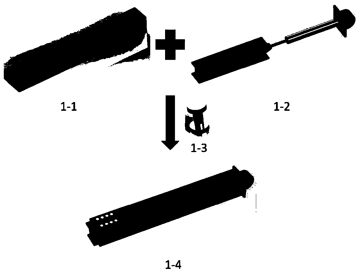
[0034] Such as figure 1 As shown, a shear key damping support capable of achieving stiffness degradation and energy consumption is characterized in that it consists of three parts: an outer casing restraint support, an embedded sliding support, and an embedded damper. A section of the outer casing restraint support and the embedded sliding support are respectively bolted or welded to the beam-column nodes of the structure, and the overlapping places are nested with each other and connected by a shear key bolt group. One end of the embedded damper is connected with the embedded sliding support by bolts or Welding, the other end is connected at the beam-column node with the outer shell restraint support.
Embodiment 2
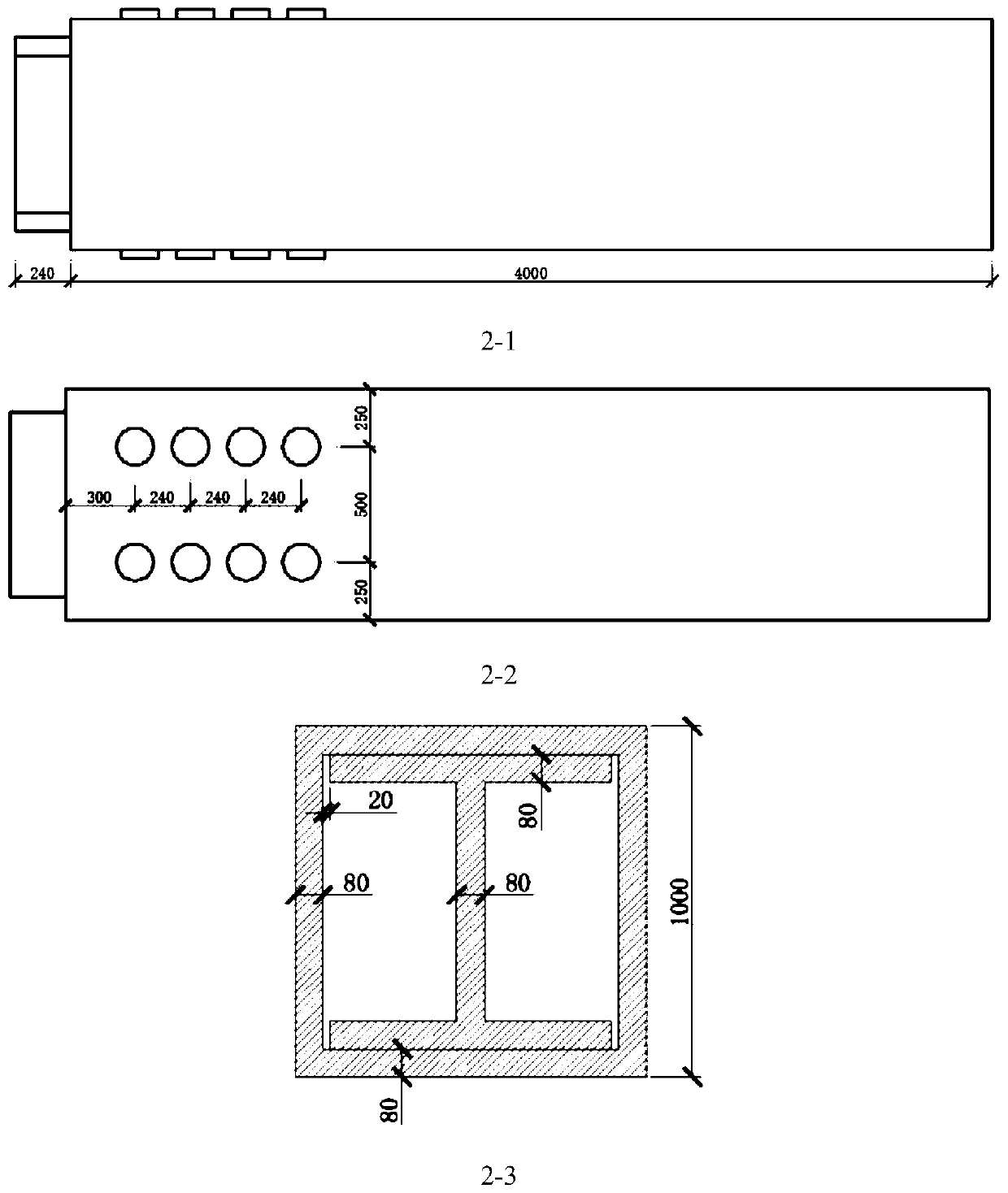
[0036] In the technical solution of the first embodiment, such as figure 2 As shown, the box-shaped steel pipe used for the outer casing restraint support has holes at one end that is not connected to the beam-column nodes. The holes are located on two opposite sides, and the holes are distributed in two rows along the axial direction of the steel pipe. The height of the I-beam used for the embedded sliding support is the same as the height of the inner edge of the box-shaped steel pipe. The flange width of the I-beam is slightly smaller than the inner edge width of the box-shaped steel pipe to prevent the steel from deforming and hindering sliding. Holes are opened at one end. The holes are located on the four flanges of the I-beam, distributed along the I-beam. The distance between the holes in the width direction of the flange is the same as the distance in the width direction of the box-shaped steel pipe.
[0037] In order to realize the shear failure resistance and replaceme...
Embodiment 3
[0040] The frame-shear key damping support structure applying the technical solution of the second embodiment is compared with the frame-anti-buckling support structure not applying the present invention. The structure arrangement is as follows Figure 4 As shown, the shear key damping support or anti-buckling support is applied to a two-story steel-reinforced concrete giant frame structure. The giant frame has a 42-meter first floor and a total structure of 84 meters high. The frame column section size is 2000×2000mm, and the steel content is 5%; the frame beam section size is 1000×2000mm, and the steel content is 2.15%. The steel is all Q390, and the concrete is all C60.
[0041] The structure is subjected to one-way static horizontal loading, and the internal force at the bottom of the frame column and the compression damage development of the concrete at the bottom of the column under pressure are extracted. Compared with the frame-anti-buckling support structure without the a...
PUM
 Abstract
Description
Claims
Application Information
 - R&D
- Intellectual Property
- Life Sciences
- Materials
- Tech Scout
- Unparalleled Data Quality
- Higher Quality Content
- 60% Fewer Hallucinations
Browse by: Latest US Patents, China's latest patents, Technical Efficacy Thesaurus, Application Domain, Technology Topic, Popular Technical Reports.
© 2025 PatSnap. All rights reserved.Legal|Privacy policy|Modern Slavery Act Transparency Statement|Sitemap|About US| Contact US: help@patsnap.com


