
Multifunctional die cutting machine of corrugated papers for cartons

A corrugated paper and multi-functional technology, applied in the field of multi-functional die-cutting machines, can solve the problems of endangering the health of workers and not removing burrs, and achieve the effects of ensuring health, low cost and strong practicability

Inactive Publication Date: 2019-02-01
温雄权
View PDF7 Cites 3 Cited by
  • Summary
  • Abstract
  • Description
  • Claims
  • Application Information

AI Technical Summary

Problems solved by technology

However, this die-cutting machine does not have the function of deburring, and the paper scraps generated during the cutting process greatly endanger the health of the staff.

Method used


Image

  • Multifunctional die cutting machine of corrugated papers for cartons
  • Multifunctional die cutting machine of corrugated papers for cartons
  • Multifunctional die cutting machine of corrugated papers for cartons

Examples


Embodiment 1

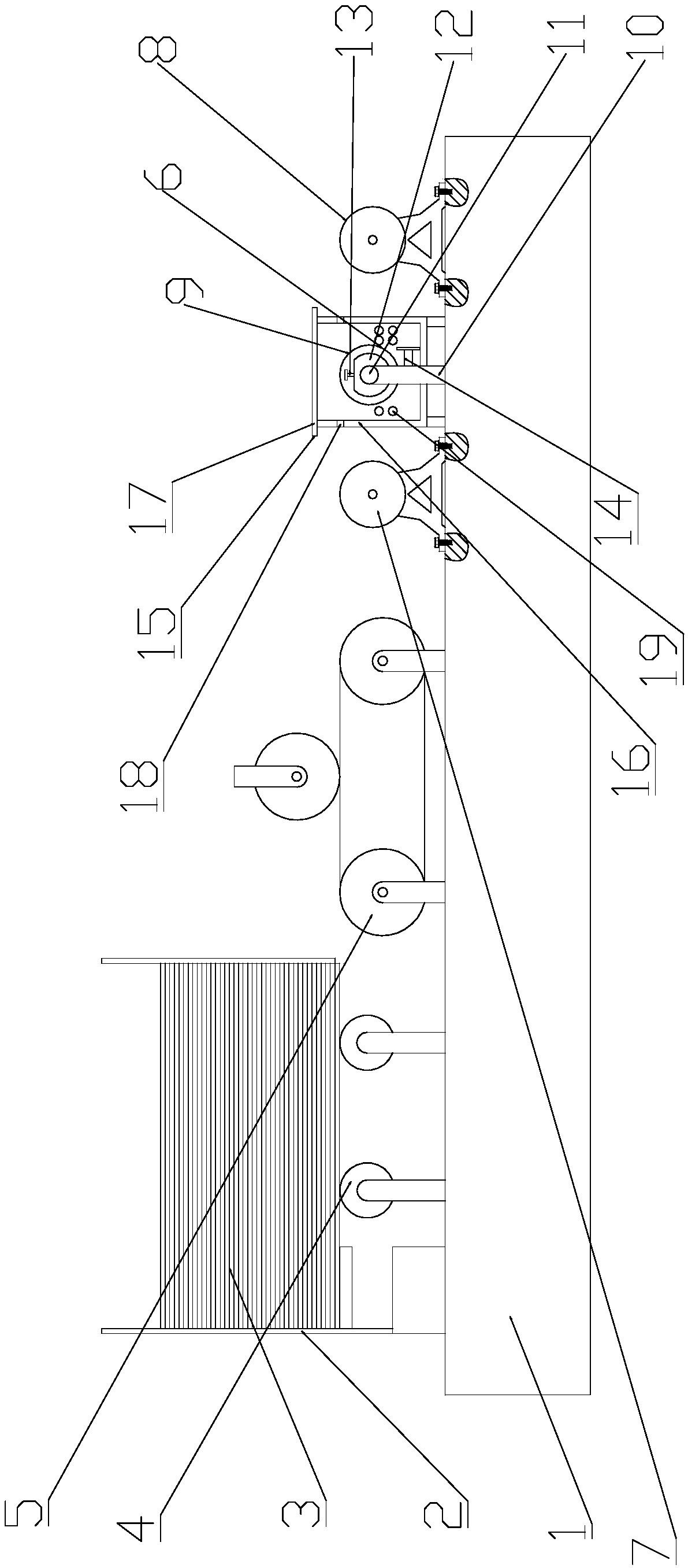
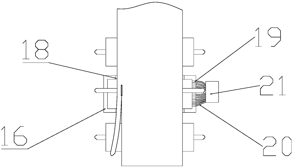
[0017] see figure 1 and figure 2 , a multifunctional die-cutting machine for corrugated paper for cartons, comprising a base 1, a raw material box 2, corrugated paper 3, a discharge roller 4, a flattening roller 5 and a cutting blade 6, and the upper left side of the base 1 is fixed with a raw material box 2. The corrugated paper 3 is placed in the raw material box 2, the bottom of the corrugated paper 3 is closely attached to the discharge roller 4, and the flattening roller 5 is arranged on the right side of the discharge roller 4. The cutting blade 6 is arranged on the right side of the flat roller 5; the left supporting roller 7 is arranged on the right side of the flattening roller 5, the right supporting roller 8 is arranged on the right side of the left supporting roller 7, and The support roller 7 and the right support roller 8 are fixed on the upper end surface of the base 1 by bolts. When the cutting blade 6 cuts the corrugated paper 3, the left support roller 7 an...

Embodiment 2

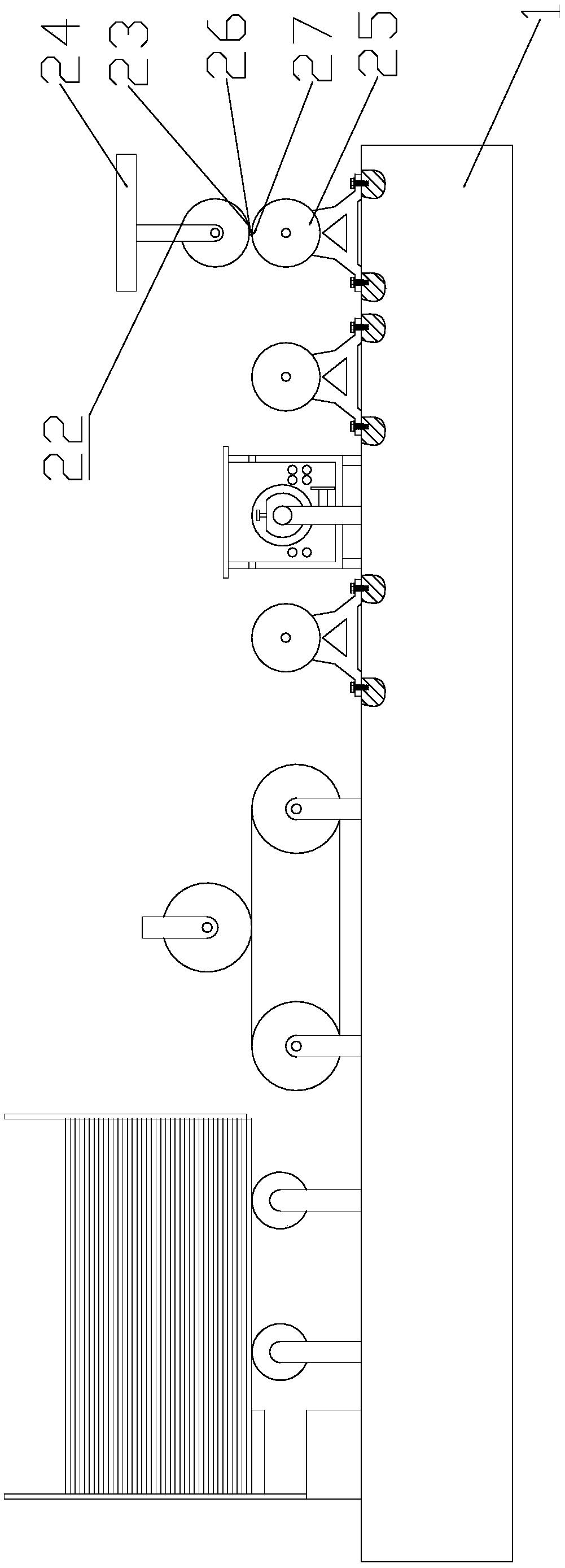
[0019] see image 3 and Figure 4 Compared with Embodiment 1, the present embodiment 2 differs only in that a length cutting mechanism 22 is arranged on the right side of the right support roller 8, and the length cutting mechanism 22 includes an upper cutting roller 23, a suspension beam 24, a lower cutting roller 25, Cutter 26 and knife groove 27, described upper cutting roller 23 bolts are fixed on the described suspension beam 24, described lower cutting roller 25 bolts are fixed on the described base 1, described upper cutting roller 23 is welded and fixed with cutting knife 26, the lower cutting roller 25 is processed with a knife groove 27; the upper cutting roller 23 and the lower cutting roller 25 rotate at the same speed and turn in the opposite direction. When passing between the cutting rollers 25, the corrugated paper 3 is cut every time the cutting knife 26 contacts the knife groove 27, and the cutting length is the outer circumference of the upper cutting rolle...


PUM


Abstract

The invention relates to the technical field of carton production equipment, in particular to a multifunctional die cutting machine of corrugated papers for cartons. The machine comprises a base, a raw material box, the corrugated papers, a discharge roller, an unfolding roller and a cutting blade; a left support roller is arranged on the right side of the unfolding roller; a right support rolleris arranged on the right side of the left support roller; the left support roller and the right support roller are fixed on the upper end surface of the base through bolts; an adjustable cutter framemechanism is arranged between the left support roller and the right support roller; and a dustproof mechanism covers the outer side of the adjustable cutter frame mechanism. The machine is simple in structure and low in cost, can synchronously realize fixed-width and fixed-length cutting of the corrugated papers to achieve speediness and convenience, meanwhile, effectively absorbs paper scraps generated during cutting, guarantees the health of workers, and is high in practicability and broad in market prospect.

Description

technical field [0001] The invention relates to the technical field of carton production equipment, in particular to a multifunctional die-cutting machine for corrugated paper used in cartons. Background technique [0002] Die-cutting machines are also called beer machines, cutting machines, and CNC punching machines. They are mainly used for die-cutting operations on materials such as corrugated paper, double-sided adhesive tape, electronics, and mobile phone pads. Die-cutting machines use steel knives, metal molds, and steel wires. Apply a certain pressure through the embossing plate to cut the printed matter or cardboard into a certain shape, which is an important equipment for post-press packaging processing. [0003] Chinese patent (notification number: CN206277463U, announcement date: 2017.06.27) discloses a die-cutting machine for corrugated cardboard. A storage chamber for placing corrugated cardboard is enclosed between the parts; the pick-up roller is arranged alo...

Claims


Application Information

Patent Timeline
Patent Type & Authority Applications(China)
IPC IPC(8): B31B50/20B31B50/74
Inventor 温雄权
Owner 温雄权
Learn More