
Bonding machine lead mechanism and working method

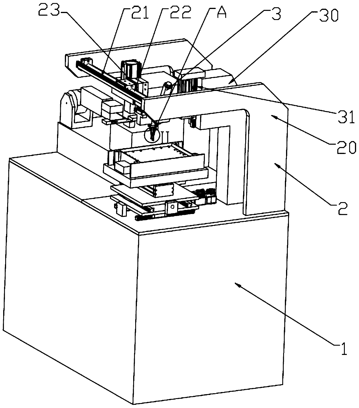
A technology of bonding machine lead and bonding machine, which is applied in the direction of electrical components, semiconductor/solid-state device manufacturing, circuits, etc., can solve the problem of low bonding efficiency and precision, affecting bonding quality and bonding efficiency, and inability to perceive metal wires Tension and other problems, to avoid the effect of excessive tension

Inactive Publication Date: 2020-04-21
南京微毫科技有限公司
View PDF0 Cites 6 Cited by
  • Summary
  • Abstract
  • Description
  • Claims
  • Application Information

AI Technical Summary

Problems solved by technology

[0002] In the process of wire bonding technology, heat, pressure, and ultrasonic waves are used to perform three thermocompression bonding at the same time to complete. When the first bonding point is completed, the lead clip moves to the second bonding point and is connected to the chip or electrode. The metal wire forms a line arc under the pressure of the lead clamp. Due to the characteristics of the metal wire itself, the metal wire forming the line arc itself has a certain tension. The tension of the metal wire and the clamping force of the line clamp directly affect the bonding quality. and bonding efficiency; the existing bonding machines are usually unable to sense the tension of the metal wire itself, so the lead clamp is used for multiple adjustments to complete the bonding, so that the bonding efficiency and accuracy are not high

Method used


Image

  • Bonding machine lead mechanism and working method
  • Bonding machine lead mechanism and working method
  • Bonding machine lead mechanism and working method

Examples


Embodiment Construction

[0026] In the following description, numerous specific details are given in order to provide a more thorough understanding of the present invention. It will be apparent, however, to one skilled in the art that the present invention may be practiced without one or more of these details. In other examples, some technical features known in the art are not described in order to avoid confusion with the present invention.

[0027] Wire bonding is one of the common and important production processes in the semiconductor industry. The applicant found that most of the existing bonding machine lead clamps control the displacement of the lead clamp and the clamping force on the lead according to the data detected by the detection components and the displacement amplifier, but Since the wire used for bonding is made of metal, and the wire itself has a certain tension during welding or molding, the tension of the wire and the clamping force of the clamp directly affect the bonding quality...


PUM


Abstract

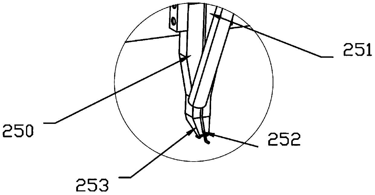
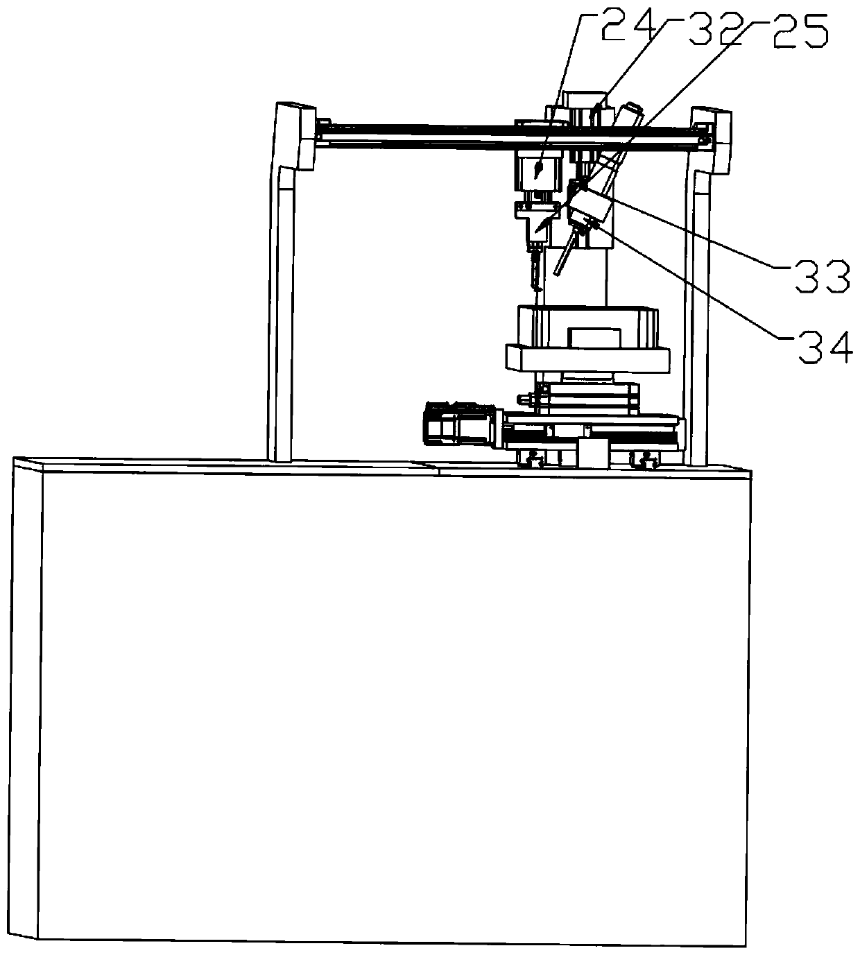
The invention discloses a bonding machine lead mechanism which is fixedly installed on a bonding machine base. The mechanism comprises an installation frame fixedly installed on the base, a lead clampfixedly connected to the installation frame and a wire feeding mechanism arranged on the base. The lead clamp comprises a displacement amplifier fixedly installed on the lead clamp, a driving motor connected with the displacement amplifier, a pair of connecting bridge plates in transmission connection with the driving motor, a left clamping jaw and a right clamping jaw, wherein the left clampingjaw and the right clamping jaw are connected to the other ends of the pair of connecting bridge plates. In the invention, a servo motor and a first stroke cylinder drive the lead clamp to adjust a metal wire output by a wire feeding part; the metal wire is welded on a chip metal layer; a tension generated by the metal wire in an adjusting process is fed back according to a tension measurement andcontrol unit; and adjusting positions of a second bonding point and the lead clamp are accurate, and welding failure caused by over-high tension of the metal wire is avoided.

Description

technical field [0001] The invention belongs to the field of bonding machine design, in particular to a bonding machine lead wire mechanism and a working method. Background technique [0002] In the process of wire bonding technology, heat, pressure, and ultrasonic waves are used to perform three thermocompression bonding at the same time to complete. When the first bonding point is completed, the lead clip moves to the second bonding point and is connected to the chip or electrode. The metal wire forms a line arc under the pressure of the lead clamp. Due to the characteristics of the metal wire itself, the metal wire forming the line arc itself has a certain tension. The tension of the metal wire and the clamping force of the line clamp directly affect the bonding quality. and bonding efficiency; the existing bonding machines are usually unable to sense the tension of the metal wire itself, so the lead clamp is used for multiple adjustments to complete the bonding, so that ...

Claims


Application Information

Patent Timeline
Patent Type & Authority Applications(China)
IPC IPC(8): H01L21/67H01L21/48
CPCH01L21/4885H01L21/67092H01L21/67121
Inventor 杜东良
Owner 南京微毫科技有限公司
Learn More