
A virtual pre-splicing tool for steel structure

A steel structure, pre-assembled technology, applied in the direction of welding equipment, manufacturing tools, auxiliary devices, etc., can solve the problems of rough weld width adjustment, internal stress changes, angle differences, etc., and achieve the effect of avoiding welding failure

Active Publication Date: 2022-07-05
CHONGQING INTERNATIONAL CONSTRUCTION CORPORATION
View PDF7 Cites 0 Cited by
  • Summary
  • Abstract
  • Description
  • Claims
  • Application Information

AI Technical Summary

Problems solved by technology

[0006] Aiming at the deficiencies of the prior art, the present invention provides a steel structure virtual pre-splicing tool, which has the advantages of steel angle adjustment, weld seam adjustment, translation locking, etc., and solves the problem that the angle difference between the welding surfaces between the steel parts causes the steel parts to The strength, torque and internal stress of the welded joints are all changed, and the level of the steel parts formed by splicing is reduced, and the steel parts cannot be moved relatively horizontally, resulting in rough adjustment of the width of the weld, etc. The problem
[0008] In order to solve the angle difference between the welding surfaces of the above steel parts, the strength, torque and internal stress of the welded joints of the steel parts will change, and the level of the steel parts formed by splicing will drop and the steel parts will not be aligned. For technical problems such as relatively rough adjustment of the width of the weld caused by relatively horizontal stable movement, the present invention provides the following technical solutions:

Method used


Image

  • A virtual pre-splicing tool for steel structure
  • A virtual pre-splicing tool for steel structure
  • A virtual pre-splicing tool for steel structure

Examples


Embodiment 1

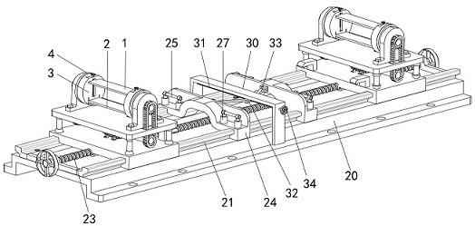
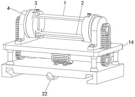
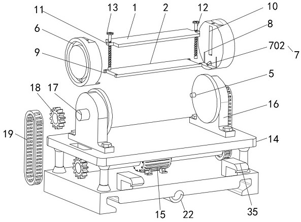
[0039] see Figure 1-3 , a steel structure virtual pre-splicing tool, including a pressure plate 1 and a firing plate 2 that can approach each other, and a pressure bearing plate 3 and a drive plate 4 that can be locked with each other;

[0040] One side of the drive plate 4 is provided with a drive column 5 , and one side of the pressure bearing plate 3 is provided with a drive ring groove 6 tangent to the drive column 5 , and the drive column 5 surrounds the drive ring groove 6. Do a circular motion, a firing member 7 is arranged in the pressure bearing plate 3, and the firing member 7 can enter the driving ring groove 6 by applying force to the firing member 7 through the firing plate 2 so that the firing member 7 can interact with the driving ring groove 6. The column 5 is in contact to realize the linkage between the drive plate 4 and the pressure plate 3 .

[0041] Therefore, before the drive plate 4 rotates, the pressure plate 3 rotates at will, so that the opposite surf...

Embodiment 2

[0056] see figure 1 and image 3 , and also includes a translation assembly, the translation assembly includes a base 20 and a slide rail 21, the slide rails 21 are fixedly installed on both sides of the upper surface of the base 20, and the slide rail 21 and the mounting seat 14 is slidingly connected, the lower surface of the mounting seat 14 is provided with a threaded seat 22, the threaded seat 22 penetrates and is threadedly connected with a translation screw 23, and the translation screw 23 is rotatably connected to the base 20;

[0057] Both ends of the mounting seat 14 are fixedly installed with hooks 35, and the translation assembly drives the mounting seat 14 to translate so that the hooks 35 are engaged with the self-locking assembly;

[0058] The self-locking assembly includes a self-locking seat 24, the self-locking seat 24 is slidably mounted on the slide rail 21, and both ends of the self-locking seat 24 are provided with clamping rods 25, and the clamping rods...

Embodiment 3

[0064] see figure 1 and image 3 , a gantry frame 30 is fixedly installed in the middle of the upper surface of the base 20, the gantry frame 30 is penetrated and is rotatably connected with a distance adjustment screw 31, and the distance adjustment screw 31 is penetrated and screwed with a distance adjustment block 32. One side of the distance adjustment block 32 is rotatably connected with a connecting plate 33, and one end of the connecting plate 33 is rotatably connected to one side of the self-locking seat 24;

[0065] A distance adjustment knob 34 is fixedly connected to one end of the distance adjustment screw 31 .

[0066] By rotating the distance adjustment knob 34, the distance adjustment knob 34 drives the distance adjustment screw 31 to rotate, so that the distance adjustment block 32 moves along the lower surface of the gantry frame 30, and then drives the self-locking seat 24 through the connecting plate 33 to move along the slide rail 21 is moved, so as to ac...


PUM


Abstract

The invention relates to the technical field of steel structure splicing, and discloses a steel structure virtual pre-splicing tool, comprising a pressure plate and a firing plate. In the present invention, before the drive plate rotates, the pressure-bearing plate is rotated at will, so that the opposite surfaces of the pressure plate and the firing plate are in contact with the surface of the steel piece, and then the steel piece is placed on the firing plate, so that the pressure plate and the firing plate are The plate completes the fixing of the steel parts, because when the pressure plate presses the steel parts, the firing parts enter the driving ring groove, and the driving columns are in contact with the firing parts to complete the clamping, so as to realize the connection between the driving plate and the pressure-bearing plate. Linkage, at this time, the angle when the drive plate and the pressure plate are linked is used as the initial value, so that the drive plate rotates to drive the steel parts to rotate, so as to achieve the problem of adjusting its levelness and avoid the steel parts when the steel parts are welded. There is an angle difference between them, which leads to the change of the strength, the torque and the internal stress of the welded joints of the steel parts, and the level of the steel parts formed by the splicing decreases.

Description

technical field [0001] The invention relates to the technical field of steel structure splicing, in particular to a steel structure virtual pre-splicing tool. Background technique [0002] Steel structure is a structure composed of steel materials and is one of the main types of building structures. The structure is mainly composed of steel beams, steel columns, steel trusses and other components made of section steel and steel plates, and adopts rust removal and rust prevention processes such as silanization, pure manganese phosphating, washing and drying, and galvanizing. Welds, bolts or rivets are usually used to connect components or parts. Because of its light weight and simple construction, it is widely used in large workshops, venues, super high-rises and other fields. The steel structure is easy to rust. Generally, the steel structure needs to be derusted, galvanized or painted, and it needs to be regularly maintained. Welding, also known as welding, is a manufact...

Claims


Application Information

Patent Timeline
Patent Type & Authority Patents(China)
IPC IPC(8): B23K37/047
CPCB23K37/047
Inventor 杨磊秦李波杨凤
Owner CHONGQING INTERNATIONAL CONSTRUCTION CORPORATION
Learn More