Virtual pre-splicing tool for steel structure
A steel structure, pre-assembled technology, applied in the direction of auxiliary devices, manufacturing tools, welding equipment, etc., can solve the problems of rough adjustment of weld width, poor angle, stable movement, etc., and achieve the effect of avoiding welding failure
- Summary
- Abstract
- Description
- Claims
- Application Information
AI Technical Summary
Problems solved by technology
Method used
Image
Examples
Embodiment 1
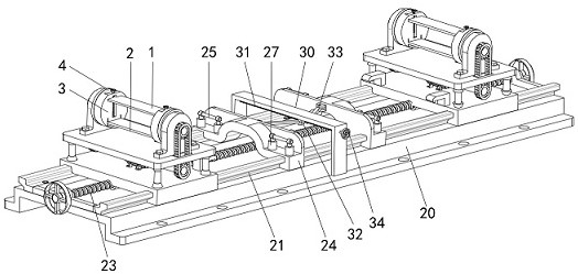
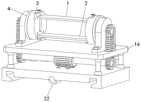
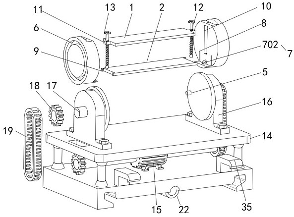
[0039] see Figure 1-3 , a steel structure virtual pre-splicing tool, including a pressure plate 1 and a firing plate 2 that can approach each other, and also includes a pressure receiving plate 3 and a driving plate 4 that can be locked with each other;
[0040] One side of the drive plate 4 is provided with a drive column 5, one side of the pressure bearing plate 3 is provided with a drive ring groove 6 tangent to the drive column 5, and the drive column 5 surrounds the drive ring groove. 6 makes a circular motion, the pressure plate 3 is provided with a firing piece 7, and the firing plate 2 exerts force on the firing piece 7 so that the firing piece 7 enters the driving ring groove 6 and can be connected with the driving The column 5 is in contact to realize the linkage between the drive plate 4 and the pressure receiving plate 3 .
[0041] Thereby, before the driving disc 4 rotates, the pressure receiving disc 3 rotates freely, so that the opposite surfaces of the pressure...
Embodiment 2
[0056] see figure 1 and image 3 , also includes a translation assembly, the translation assembly includes a base 20 and a slide rail 21, the slide rails 21 are respectively fixedly installed on both sides of the upper surface of the base 20, and the slide rail 21 and the mounting seat 14 is slidingly connected, the lower surface of the mounting seat 14 is provided with a threaded seat 22, the threaded seat 22 penetrates and is threadedly connected with a translation screw 23, and the translation screw 23 is rotatably connected to the base 20;
[0057] Both ends of the mounting base 14 are fixedly equipped with hooks 35, and the translation assembly drives the mounting base 14 to translate so that the hooks 35 are engaged with the self-locking assembly;
[0058] Described self-locking assembly comprises self-locking seat 24, and described self-locking seat 24 is slidably installed on described slide rail 21, and the two ends of described self-locking seat 24 are all provided ...
Embodiment 3
[0064] see figure 1 and image 3 A gantry 30 is fixedly installed in the middle of the upper surface of the base 20, the gantry 30 penetrates and is rotatably connected with a distance adjusting screw 31, and the distance adjusting screw 31 penetrates and is threadedly connected with a distance adjusting block 32, the One side of the distance adjustment block 32 is rotatably connected with a connecting plate 33, and one end of the connecting plate 33 is rotatably connected to one side of the self-locking seat 24;
[0065] One end of the pitch adjusting screw 31 is fixedly connected with a pitch adjusting knob 34 .
[0066] By turning the distance adjustment knob 34, the distance adjustment knob 34 drives the distance adjustment screw rod 31 to rotate, so that the distance adjustment block 32 moves along the lower surface of the gantry 30, and then the self-locking seat 24 is driven by the connecting plate 33 to move along the slide rail. 21 to move, so as to achieve the purp...
PUM
 Abstract
Description
Claims
Application Information
 - R&D Engineer
- R&D Manager
- IP Professional
- Industry Leading Data Capabilities
- Powerful AI technology
- Patent DNA Extraction
Browse by: Latest US Patents, China's latest patents, Technical Efficacy Thesaurus, Application Domain, Technology Topic, Popular Technical Reports.
© 2024 PatSnap. All rights reserved.Legal|Privacy policy|Modern Slavery Act Transparency Statement|Sitemap|About US| Contact US: help@patsnap.com


