
Power supply system for power system monitoring equipment

A technology for monitoring equipment and power supply systems, applied in battery circuit devices, current collectors, electric vehicles, etc., can solve problems such as inconvenience of staff and short battery power supply time, so as to reduce the number of replacements, ensure power supply continuity, and reduce power supply. cost effect

Active Publication Date: 2019-01-29
ELECTRIC POWER RESEARCH INSTITUTE, CHINA SOUTHERN POWER GRID CO LTD +1
View PDF8 Cites 4 Cited by
  • Summary
  • Abstract
  • Description
  • Claims
  • Application Information

AI Technical Summary

Problems solved by technology

The common power supply method in the prior art is to use battery power supply, but the battery power supply has the problem of short power supply time, so the battery needs to be replaced frequently, which brings inconvenience to the staff

Method used


Image

  • Power supply system for power system monitoring equipment
  • Power supply system for power system monitoring equipment

Examples


Embodiment Construction

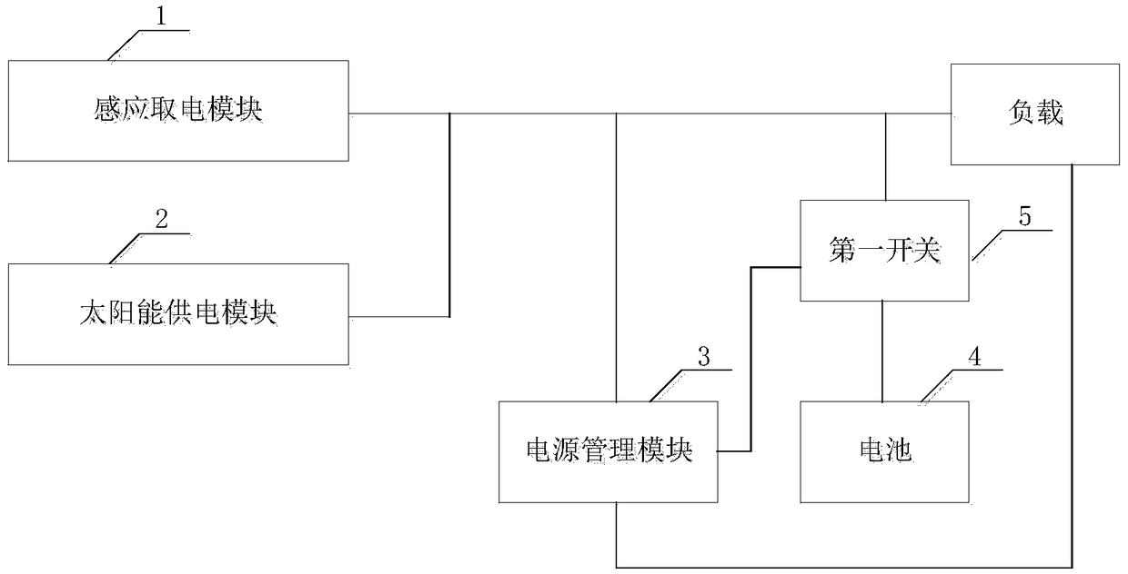
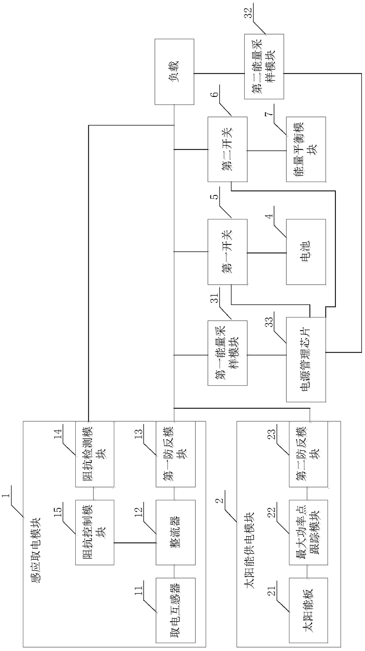
[0039] The core of the present invention is to provide a power supply system for power system monitoring equipment, which ensures the continuity of power supply, reduces the number of battery replacements, and brings convenience to the staff; in addition, due to the participation of solar power supply, the cost of power supply is reduced.

[0040] In order to make the purpose, technical solutions and advantages of the embodiments of the present invention clearer, the technical solutions in the embodiments of the present invention will be clearly and completely described below in conjunction with the drawings in the embodiments of the present invention. Obviously, the described embodiments It is a part of embodiments of the present invention, but not all embodiments. Based on the embodiments of the present invention, all other embodiments obtained by persons of ordinary skill in the art without making creative efforts belong to the protection scope of the present invention.

[...


PUM


Abstract

The invention discloses a power supply system for power system monitoring equipment. The power supply system comprises an inductive power taking module, a solar power supply module, a battery and a power management module, wherein the power management module controls a first switch to switch off when energy of the inductive power taking module or the solar power supply module is greater than energy required by a load; and the power management module controls a first switch to switch on when energy of the inductive power taking module and the solar power supply module is less than energy required by the load, so that the battery supplies power to the load. The power supply system provided by the invention adopts the power supply method of combining inductive power taking, solar power supplyand battery, preferentially uses the power of the inductive power taking module and the solar power supply module and then uses the power of the battery, thus ensures the power supply continuity, reduces the number of battery replacements, and brings convenience to the staff; in addition, due to the participation of solar power supply, the cost of power supply is reduced.

Description

technical field [0001] The invention relates to the technical field of power supply, in particular to a power supply system for power system monitoring equipment. Background technique [0002] Smart grid has become a new trend in the development of the world's power grids. Faced with new challenges and new situations, the State Grid Corporation of my country proposed to accelerate the construction of UHV as the backbone grid, coordinate the development of power grids at all levels, and integrate information technology, automation, The strategic goal of a strong smart grid characterized by interaction. According to the demand of smart grid, intelligent monitoring equipment will be widely promoted and applied. In the application scenarios such as outdoor suburbs without wired power supply, how to provide safe and stable power supply for monitoring equipment is the first problem that intelligent monitoring equipment must face when it is widely used. question. A common power su...

Claims


Application Information

Patent Timeline
Patent Type & Authority Applications(China)
IPC IPC(8): H02J7/35H02J50/10
CPCH02J7/35H02J50/10
Inventor 李鹏许爱东李立浧王志明明哲曹扬
Owner ELECTRIC POWER RESEARCH INSTITUTE, CHINA SOUTHERN POWER GRID CO LTD
Learn More