Storage battery charging and discharging power supply apparatus

A charge-discharge power supply, charge-discharge circuit technology, applied to battery circuit devices, circuit devices, collectors, etc., can solve the problems of complex discharge control circuit, high cost, and inability to adjust the discharge current arbitrarily, and achieve reasonable design. The effect of discharge safety

Inactive Publication Date: 2019-01-29
双新电器(郑州)制造有限公司
View PDF0 Cites 0 Cited by
  • Summary
  • Abstract
  • Description
  • Claims
  • Application Information

AI Technical Summary

Problems solved by technology

[0003] The existing battery pulse charging and discharging power supply is generally composed of high-frequency switching power supply. The disadvantage of this kind of power supply is that it is very expensive and it is difficult to achieve high power output, so it has great limitations.
Some battery charging devices connect a discharge resistor in parallel between the positive and negative poles of the battery and design a corresponding switch control circuit to realize pulse charge and discharge. The disadvantage is that the discharge control circuit is complicated and the discharge current cannot be adjusted arbitrarily.
In a word, none of the existing battery pulse charge and discharge power supplies is ideal, and has disadvantages such as complex structure, high manufacturing cost, and low control accuracy. Therefore, in view of these problems, a battery charge and discharge power supply device is provided

Method used


Image

  • Storage battery charging and discharging power supply apparatus
  • Storage battery charging and discharging power supply apparatus
  • Storage battery charging and discharging power supply apparatus

Examples


Embodiment Construction

[0019] The following will clearly and completely describe the technical solutions in the embodiments of the present invention with reference to the accompanying drawings in the embodiments of the present invention. Obviously, the described embodiments are only some, not all, embodiments of the present invention. Based on the embodiments of the present invention, all other embodiments obtained by persons of ordinary skill in the art without making creative efforts belong to the protection scope of the present invention.

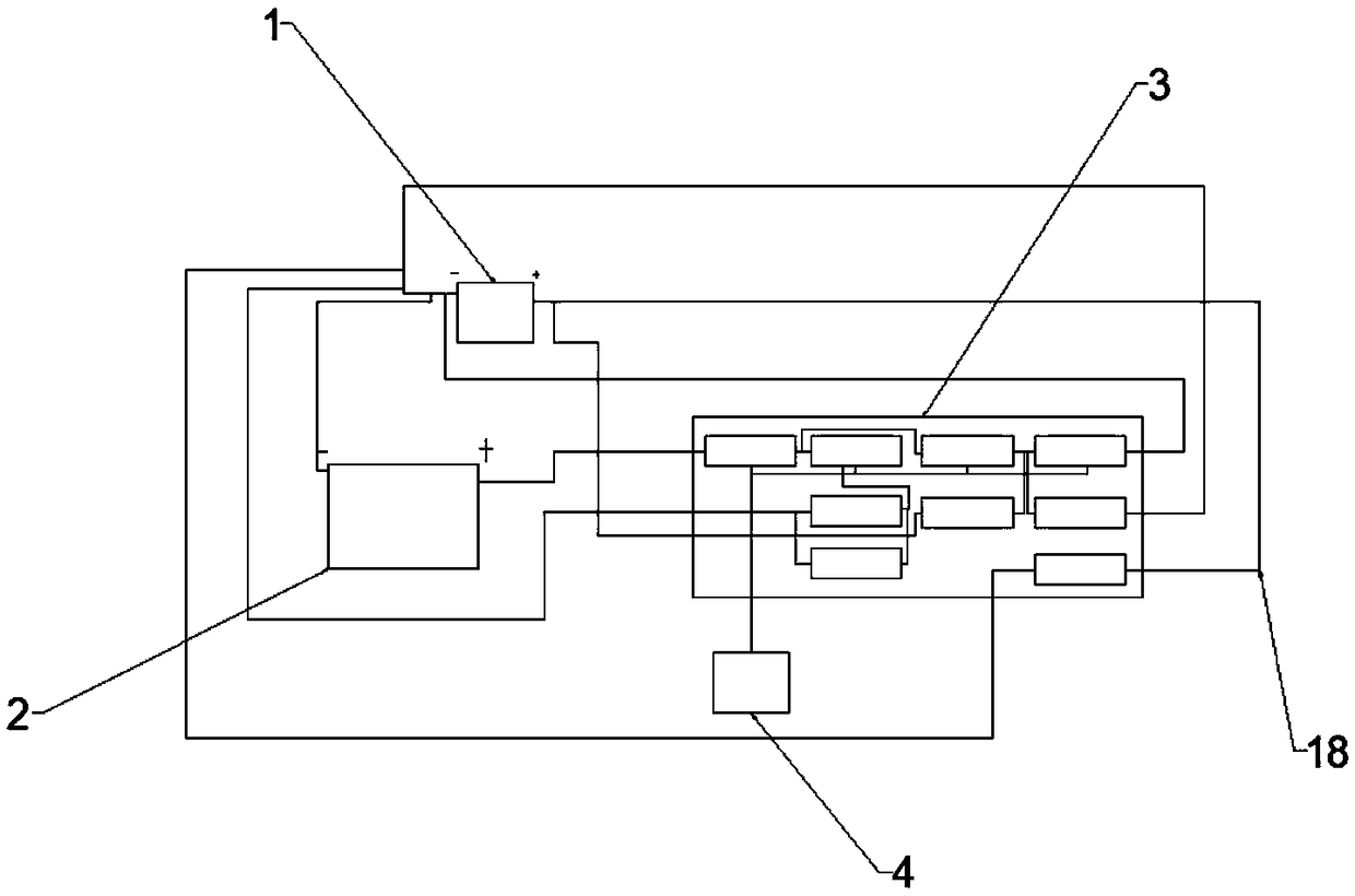
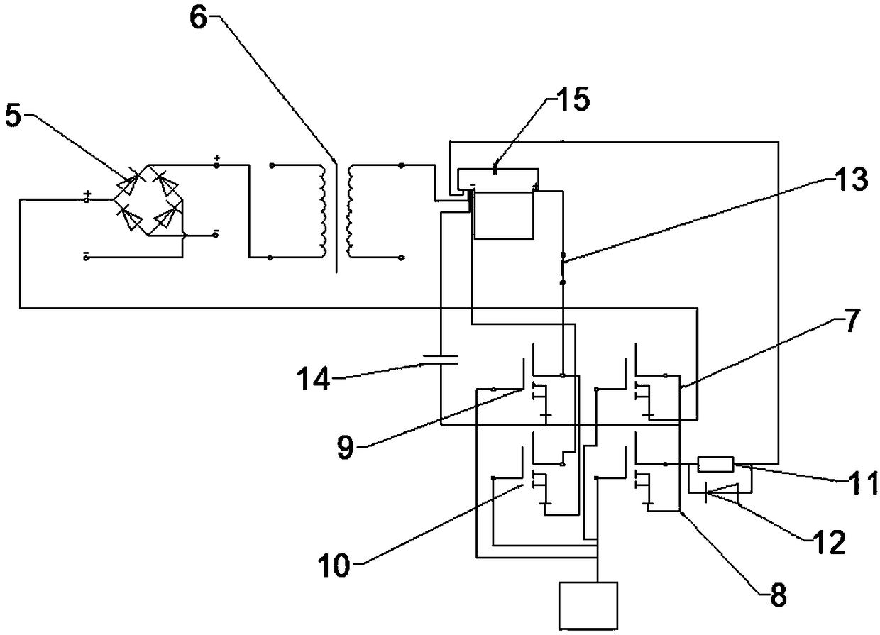
[0020] see Figure 1~3 , a storage battery charging and discharging power supply device, including a storage battery 1, an AC / DC power supply 2 and a charging and discharging circuit 3, the negative pole of the storage battery 1 is connected to the negative pole of the AC / DC power supply 2 through a transmission line 18, and the switching tube-7 The source is connected to the positive pole of the AC / DC power supply 2 through the transmission line 18, and the d...


PUM


Abstract

The invention discloses a storage battery charging and discharging power supply apparatus, which comprises a storage battery, an AC / DC power supply, a charging and discharging circuit, a controller, atransformer, a rectifier bridge, a switch tube I, a switch tube II, a switch tube III, a switch tube IV, a discharging resistor, a fast recovery diode, an inductor, a capacitor I, a capacitor II, anAC power supply, a charging and discharging circuit input terminal and transmission lines. The beneficial effects of the invention are that a source electrode of the switch tube I is connected with apositive electrode of the AC / DC power supply through the transmission line, a drain electrode of the switch tube I is connected with a source electrode of the switch tube II and a source electrode ofthe switch tube III through the transmission line, information transmitted by the switch tube I through the controller is sent out through the transmission line so as to accomplish working requirements of the apparatus, a drain electrode of the switch tube II is connected with a negative electrode of the storage battery through the discharging resistor, the fast recovery diode is reversely connected to the discharging resistor in parallel through the transmission line, and the discharging resistor is set to be an RT1-type ordinary carbon film resistor, thereby helping the apparatus to shunt, and enabling the charging and discharging of the apparatus to be more effective.

Description

technical field [0001] The invention relates to a power supply device, in particular to a storage battery charging and discharging power supply device. Background technique [0002] The charging power supply is used in the formation, charging and maintenance of the battery. The performance of the charging power supply is directly related to the working performance, service life, energy utilization efficiency and environmental protection performance of the battery. The use of pulse charging power can significantly improve the formation and charging efficiency of the battery. During the charging process, the method of short-time discharge to eliminate the polarization of the battery can prevent a large amount of gas and heat from being generated in the battery, thereby greatly shortening the charging time. [0003] The existing battery pulse charging and discharging power supply is generally composed of high-frequency switching power supply. The disadvantage of this kind of p...

Claims


Application Information

Patent Timeline
IPC IPC(8): H02J7/04
CPCH02J7/045
Inventor 宋万生耿同明
Owner 双新电器(郑州)制造有限公司
Why Eureka
Try Eureka