A vibration mixing device for chemical reagents
A chemical reagent and mixing technology, which is applied in the field of chemical reagent vibration and mixing devices, can solve the problems of not having multiple chemical reagent vibration experiments, lack of experimental effect comparison, etc.
- Summary
- Abstract
- Description
- Claims
- Application Information
AI Technical Summary
Problems solved by technology
Method used
Image


Examples
specific Embodiment approach 1
[0029] Combine below Figure 1-11Description of this embodiment, an oscillating and mixing device for chemical reagents, including a base 1, a vertical support 2, a side slide frame 3, a reciprocating slide 4, a fixed seat 5, a hinged rod 6 and a drive assembly 7, the vertical The support base 2 is slidably connected to the base 1, the vertical support base 2 is connected to the base 1 by transmission, the two side sliding frames 3 are symmetrically fixedly connected to both ends of the vertical support base 2, and the two reciprocating slide bases 4 are respectively slidably connected to the two On the side sliding frame 3, the lower ends of the two reciprocating sliding seats 4 are respectively connected to the two side sliding frames 3, and the two reciprocating sliding seats 4 are respectively slidably connected with two fixing seats 5, and the upper ends of the two hinge rods 6 are respectively Hinged on the vertical support base 2, the lower ends of the two hinged rods 6...
specific Embodiment approach 2
[0031] Combine below Figure 1-11 To illustrate this embodiment, the base 1 includes a bottom plate 1-1, a left L-shaped seat 1-2, a right L-shaped seat 1-3, a rack I1-4 and a rack II1-5; the left L-shaped seat 1- 2 and the right L-shaped seat 1-3 are symmetrically fixedly connected to both ends of the bottom plate 1-1, the rack I1-4 is fixedly connected to the top surface of the left L-shaped seat 1-2, and the rack II1-5 is fixedly connected to the bottom plate 1 -1, rack II 1-5 is located between the left L-shaped seat 1-2 and the right L-shaped seat 1-3; the left L-shaped seat 1-2 and the right L-shaped seat 1-3 have played a role in the vertical support The role of support and limit.
specific Embodiment approach 3
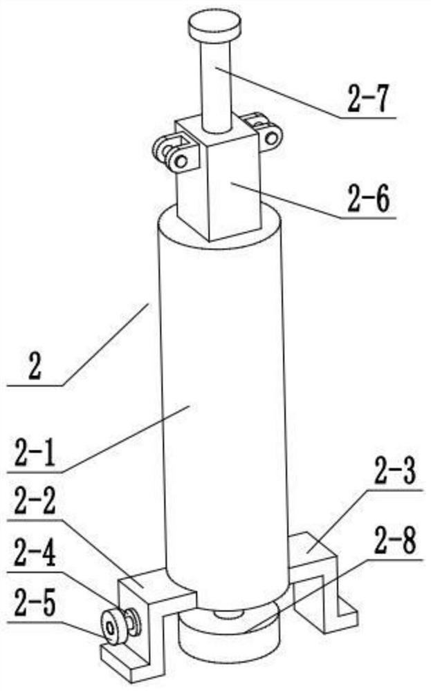
[0033] Combine below Figure 1-11 To illustrate this embodiment, the vertical support seat 2 includes a support column 2-1, a left Z-shaped seat plate 2-2, a right Z-shaped seat plate 2-3, a motor 2-4, a driving gear 2-5, a rectangular telescopic Rod 2-6, externally threaded rod 2-7 and central gear 2-8; the left and right ends of support column 2-1 are respectively fixedly connected with left Z-shaped seat plate 2-2 and right Z-shaped seat plate 2-3, left Z-shaped seat plate 2-3, The lower ends of the type seat plate 2-2 and the right Z-shaped seat plate 2-3 are respectively slidingly fitted and connected in the left L-shaped seat 1-2 and the right L-shaped seat 1-3, and the motor 2-4 is fixedly connected with the left Z-shaped seat The middle end of the plate 2-2, the driving gear 2-5 is fixedly connected to the output shaft of the motor 2-4, the driving gear 2-5 is meshed with the rack I1-4 for transmission, and the upper end of the support column 2-1 is provided with a rec...
PUM
 Abstract
Description
Claims
Application Information
 - Generate Ideas
- Intellectual Property
- Life Sciences
- Materials
- Tech Scout
- Unparalleled Data Quality
- Higher Quality Content
- 60% Fewer Hallucinations
Browse by: Latest US Patents, China's latest patents, Technical Efficacy Thesaurus, Application Domain, Technology Topic, Popular Technical Reports.
© 2025 PatSnap. All rights reserved.Legal|Privacy policy|Modern Slavery Act Transparency Statement|Sitemap|About US| Contact US: help@patsnap.com