Heating insole based on printed electronics

A technology for printing electronics and insoles, applied in the field of insoles, can solve the problems of reducing the service life of electric heating insoles, inconvenient cleaning, waste of resources, etc., and achieve the effects of mass production, resource saving, and light size.

Pending Publication Date: 2019-01-29
SHANGHAI PUBLISHING & PRINTING COLLEGE
View PDF8 Cites 0 Cited by
  • Summary
  • Abstract
  • Description
  • Claims
  • Application Information

AI Technical Summary

Problems solved by technology

Chemical heating insoles are generally disposable, which wastes resources; electric heating insoles need to carry an additional charging device, which is inconvenient to use, and because the electric heating insoles are equipped with built-in circuits and batteries, they are not easy to bend and clean, reducing the cost of electric heating insoles. service life

Method used


Image

  • Heating insole based on printed electronics
  • Heating insole based on printed electronics
  • Heating insole based on printed electronics

Examples


Embodiment 1

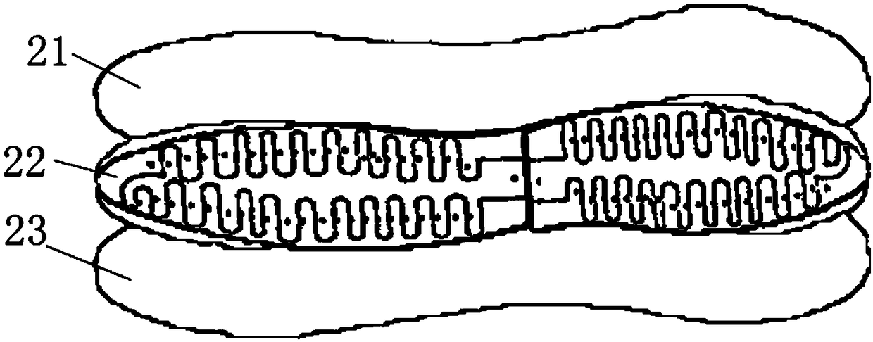
[0028] A heat-generating insole based on printed electronics, such as figure 1 As shown, it includes insole outer layer 1, heating layer 2, power supply layer 3, insole bottom layer 4 stacked in sequence from top to bottom, and a control switch 5 arranged between heating layer 2 and power supply layer 3. The outer layer 1 of the insole is located at the top and directly contacts the sole of the user's foot, and the bottom layer of the insole 4 is located at the bottom and directly contacts the inner bottom surface of the shoe. The outer layer of the insole 1 and the bottom layer of the insole 4 are used to protect the heating layer 2 and the power supply layer 4, and at the same time make the user more comfortable when using it. Compared with the power supply layer 3, the heating layer 2 is closer to the outer layer 1 of the insole, so that the heat emitted by the heating insole is more easily transmitted to the sole of the user. The outer layer 1 of the insole, the heating l...

Embodiment 2

[0036] Compared with Embodiment 1, the heating insole based on printed electronics in this embodiment has the following differences: such as image 3 As shown, the power supply circuit 32 includes three power sources 321 and three adjustment switches 322 , and the power sources 321 and the adjustment switches 322 correspond one to one. The negative poles of all the power supplies 321 are connected to each other, and the positive poles of the power supplies 321 are respectively connected to one end of the corresponding adjustment switch 322, and the other ends of the adjustment switches 322 are connected to each other, so that each power supply 321 forms a parallel group with the corresponding adjustment switch 322, and all parallel connections The groups are connected in parallel to form a power supply circuit 32 , and the two ends of any parallel group are taken out as terminals of the power supply circuit 32 . The three regulating switches 322 are all single-stage pressure s...


PUM


Abstract

The invention discloses a heating insole based on printed electronics. The heating insole based on the printed electronics comprises an insole outer layer, a power supply heating layer and an insole bottom layer. The power supply heating lay is positioned between that insole outer layer and the insole bottom layer. The power supply heating layer is provided with a power supply circuit, a control switch and a heating circuit. The power supply circuit is provided with power supply. The control switch is connected with the power supply circuit and the heating circuit. A circuit of the power supply circuit and the heating circuit are both arranged on the power supply heating layer in a printing mode, and paper batteries or a battery pack formed by parallel connection of paper batteries are adopted in the power supply. The heating insole based on the printed electronics is light in volume while realizing spontaneous heat generation of the insole, does not need to additionally carry a charging device, and does not affect the experience of consumers. The heating insole based on the printed electronics can be reused except for the paper batteries, resources are saved, and more environmental protection is achieved.

Description

technical field [0001] The invention relates to an insole, in particular to a heating insole based on printed electronics. Background technique [0002] The soles of the feet are far away from the heart and have less blood supply. The surface of the feet has a close nerve connection with the upper respiratory tract, especially the nasal mucosa. Keeping feet warm can stimulate nerve endings, accelerate blood circulation, supply sufficient nutrients to feet, promote metabolism of foot cells, and help eliminate fatigue symptoms such as soreness, numbness, pain and discomfort in legs and feet. In the cold winter, special attention needs to be paid to keeping the feet warm. It is very meaningful to design a light-weight insole that can heat itself. [0003] Existing heating insoles are divided into chemical heating insoles and electric heating insoles. Chemical heating insoles are generally disposable, which wastes resources; electric heating insoles need to carry an additional...

Claims


Application Information

Patent Timeline
Patent Type & Authority Applications(China)
IPC IPC(8): A43B17/00H05B3/34H05B3/02
CPCA43B17/00H05B3/02H05B3/34
Inventor 金琳秦晓楠周磊张奎永石俊林
Owner SHANGHAI PUBLISHING & PRINTING COLLEGE
Why Eureka
Try Eureka