
Silicon drift detector based on surface electric field control and design method thereof

A technology for silicon drift detectors and control surfaces, applied in circuits, electrical components, semiconductor devices, etc., can solve problems such as poor drift electric field, leakage current, and excessive dead zone

Pending Publication Date: 2019-01-25
XIANGTAN UNIV
View PDF0 Cites 3 Cited by
  • Summary
  • Abstract
  • Description
  • Claims
  • Application Information

AI Technical Summary

Problems solved by technology

[0006] Another object of the present invention is to provide a design method based on a silicon drift detector controlling the surface electric field, so as to realize the design of a high-quality SDD with the best drift electric field and the minimum surface current, and solve the leakage current of the SDD And design defects such as excessive dead zone and poor drift electric field

Method used


Image

  • Silicon drift detector based on surface electric field control and design method thereof
  • Silicon drift detector based on surface electric field control and design method thereof
  • Silicon drift detector based on surface electric field control and design method thereof

Examples


Embodiment Construction

[0106] The following will clearly and completely describe the technical solutions in the embodiments of the present invention with reference to the accompanying drawings in the embodiments of the present invention. Obviously, the described embodiments are only some, not all, embodiments of the present invention. Based on the embodiments of the present invention, all other embodiments obtained by persons of ordinary skill in the art without making creative efforts belong to the protection scope of the present invention.

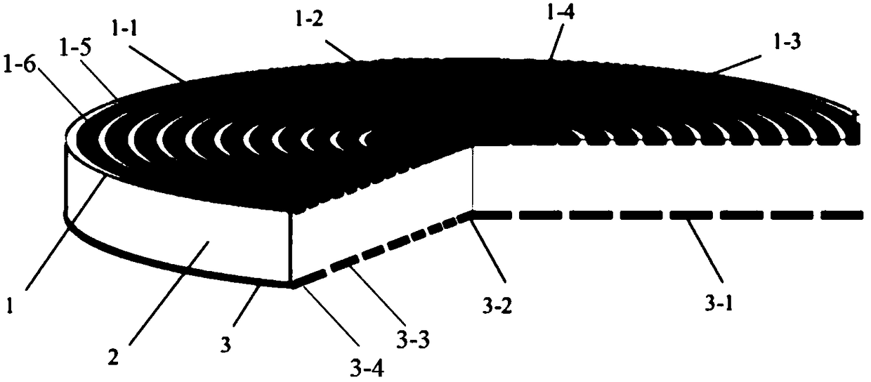
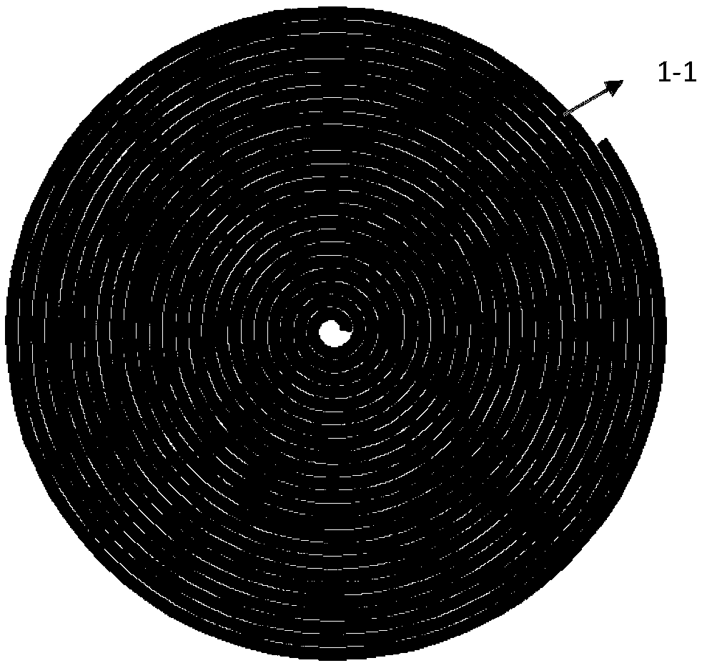
[0107] A silicon drift detector based on a controlled surface electric field, such as figure 1 As shown, it consists of a front surface electrode 1, a cylindrical n-type silicon body 2 and a rear surface electrode 3; the front surface electrode 1 is connected to a bottom surface of the cylindrical n-type silicon body 2; the rear surface electrode 3 is connected to the cylindrical n-type silicon body The other bottom surface of the silicon body 2 is connected; ...


PUM


Abstract

The invention discloses a silicon drift detector based on a control surface electric field and a design method thereof. The silicon drift detector based on the control surface electric field comprisesa front surface electrode, a cylindrical n-type silicon main body and a back surface electrode which are connected in turn. First, according to the resistance value of the first P + type circular spiral cathode ring of the front surface electrode at the radial r point, determining a voltage distribution of a first P + type circular helical cathode ring, and then keeping the gap between two adjacent rings of the first P +-type circular spiral cathode ring unchanged, determining a width distribution of a first P + type circular helical cathode ring at a radial r point, and then determining therelationship between the rotation angle of the first P + type circular helical cathode ring of the front surface electrode and the radial r point, Secondly, the drift path and the drift electric fieldof the second P +-type spiral cathode ring of the rear surface electrode are determined. Finally, the design of the second P +-type spiral cathode ring of the rear surface electrode is determined according to the design method of the first P +-type spiral cathode ring.

Description

technical field [0001] The invention belongs to the technical field of pulsar X-ray detection and the establishment of a large database for navigation systems, and in particular relates to a large-area cylindrical spiral that achieves the best drift electric field and the minimum surface current based on controlling the surface electric field and the silicon oxide / silicon interface area. Gap double-sided silicon drift detector and its design method. Background technique [0002] Since the 1960s, semiconductor detectors have been developed and applied to nuclear radiation detection. So far, several generations have been developed, and their performance has been continuously improved. Commonly used semiconductor detectors include: gold-silicon surface barrier detectors, lithium drift detectors Si(Li), Si-PIN Photodiode Detector, Silicon Drift Detector (SDD). The working principle of the silicon drift detector (SDD) is to make an N-type high-resistance silicon wafer as a subst...

Claims


Application Information

Patent Timeline
IPC IPC(8): H01L31/0224H01L31/115
CPCH01L31/022416H01L31/115
Inventor 李正匡凤兰
Owner XIANGTAN UNIV
Learn More