
Optical remote sensing image target detection method based on extended residual convolution

An optical remote sensing image and target detection technology, applied in the field of image processing, can solve the problems of large network feature receptive field, low resolution, large optical remote sensing image size, etc., and achieve the effect of improving detection accuracy and improving accuracy.

Active Publication Date: 2019-01-25
XIDIAN UNIV
View PDF7 Cites 27 Cited by
  • Summary
  • Abstract
  • Description
  • Claims
  • Application Information

AI Technical Summary

Problems solved by technology

This method can accurately and richly represent the features of the target, and can well extract the target candidate frame, and reduce the candidate frame extraction time by sharing the convolution parameters. However, this method still has the disadvantage that due to the size of the optical remote sensing image Large and low resolution, especially in the detection of ships, the ship target is small and the characteristics of the ship are often similar to the characteristics of some long buildings or large vehicle containers, which makes this method difficult to perform optical remote sensing image targets. Objects on land are often misdetected as ships during detection
However, the shortcomings of this method are: first, the detection process is divided into multiple parts in the target detection, and different networks are used for detection and segmentation, which leads to high complexity of the method
Second, due to multiple downsampling when the network extracts features, the receptive field of the network features is too large, which is not conducive to the regression task

Method used


Image

  • Optical remote sensing image target detection method based on extended residual convolution
  • Optical remote sensing image target detection method based on extended residual convolution
  • Optical remote sensing image target detection method based on extended residual convolution

Examples


Embodiment 1

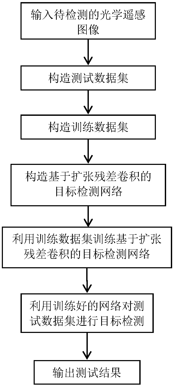
[0032] In the prior art, due to the large size and low resolution of optical remote sensing images, especially in the detection of ships, the ship targets are small and the ship’s characteristics are often similar to those of some elongated buildings or large vehicle containers. As a result, this method often mistakenly detects objects on land as ships when detecting objects in optical remote sensing images. In view of this phenomenon, the present invention provides a deep convolutional network optical remote sensing image target detection method based on dilated residual convolution, see figure 1 The present invention uses expanded residual convolution and feature fusion in a deep convolutional network, and extracting features is more suitable for target detection tasks and can improve the accuracy of target detection in optical remote sensing images, including the following steps:

[0033] (1) Construct a test data set:

[0034] (1a) Use a window with a window size of 768×768×3 p...

Embodiment 2

[0052] The deep convolutional network optical remote sensing image target detection method based on dilated residual convolution is the same as that in Example 1-1. The test data set naming rule in step (1b) refers to each file to be cut for detecting optical remote sensing images The name and the corresponding windowing steps of the cutting data block are connected by the English underscore "_" symbol to form a .jpg file format.

Embodiment 3

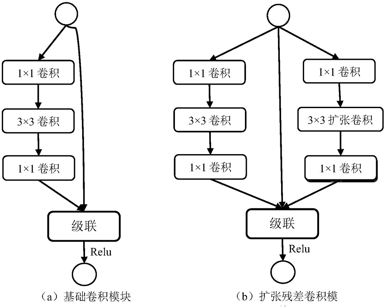
[0054] The deep convolutional network optical remote sensing image target detection method based on dilated residual convolution is the same as in embodiment 1-2, the basic convolution module in step (3a) refers to: using 1×1 and 3×3 convolution kernels Build the basic convolution module, see figure 2 (a), the basic convolution module has three layers, and its block structure is: input layer → first convolution layer → second convolution layer → third convolution layer → output layer, input layer and output layer are cascaded →Final output layer.

[0055] The basic convolution module can be divided into four types according to the parameters of each convolution layer in the basic convolution module: basic convolution module one, basic convolution module two, basic convolution module three, and basic convolution module four.

[0056] The four basic convolution module parameters are as follows:

[0057] In the basic convolution module 1, the total number of feature maps of the first ...


PUM


Abstract

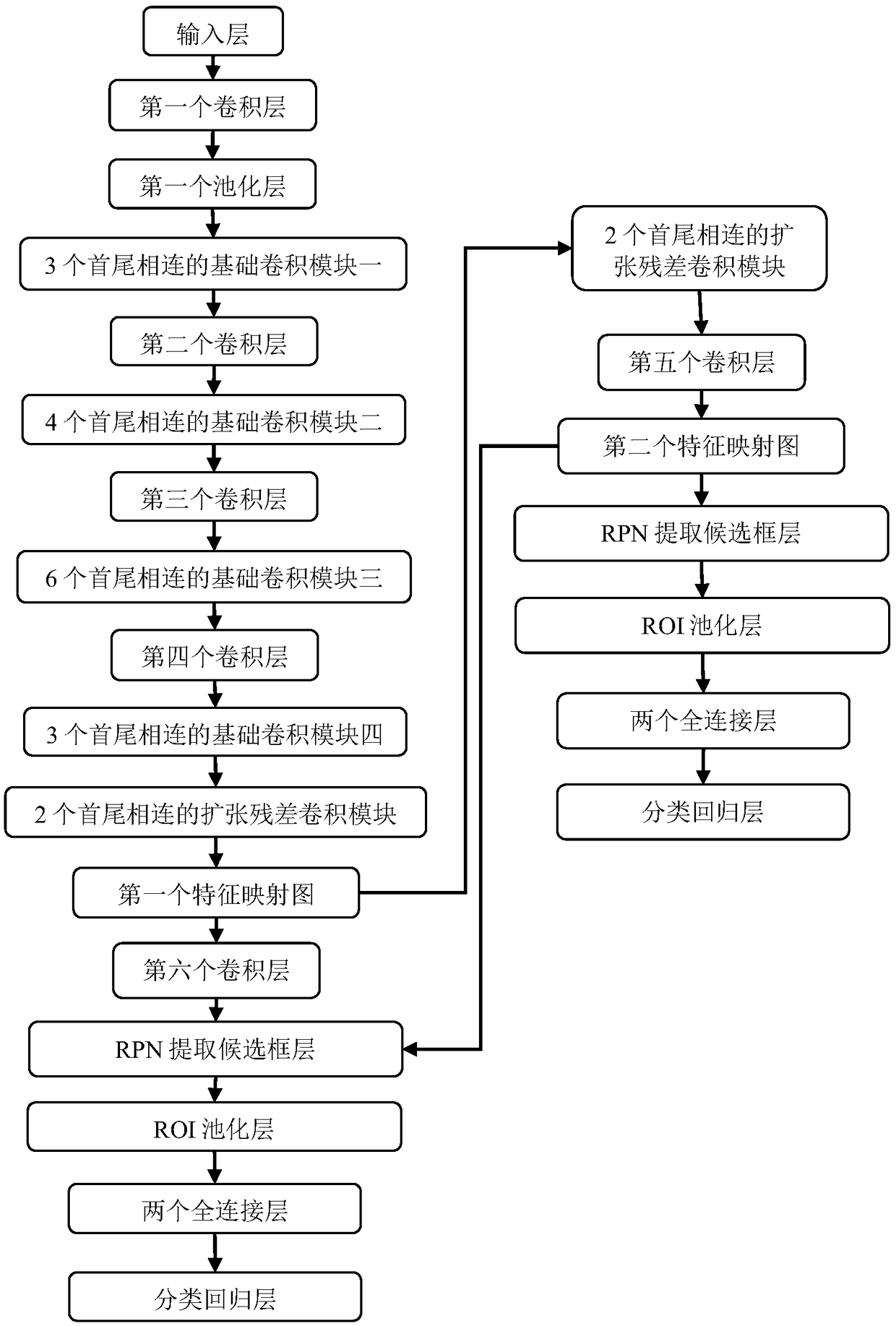
The invention discloses a depth convolution network optical remote sensing image target detection method based on extended residual convolution, which solves the problems of low detection accuracy rate and high false alarm rate of optical remote sensing image plane and ship in the prior art. The implementation steps are as follows: constructing a test data set; construct training data set; constructing a target detection network based on extended residual convolution for extended feature receptive field,training target detection network based on extended residual convolution using training data set; using the trained target detection network based on extended residual convolution to detect the target from the test data set, outputting test results. The network constructed by the inventionis more suitable for target detection of an optical remote sensing image by using an expanded residual convolution module and feature fusion, and not only improves the accuracy of a common target, butalso obviously improves the accuracy of small target detection for the optical remote sensing image. The method is used for object detection in optical remote sensing images.

Description

Technical field [0001] The present invention belongs to the technical field of image processing, and further relates to an optical remote sensing image target detection technology, in particular to an optical remote sensing image target detection method based on dilated residual convolution. The invention can be applied to the ground object detection of aircraft and ships in different regions of the optical remote sensing image. Background technique [0002] Target detection technology is one of the core issues in the field of computer vision. Remote sensing target detection uses images captured by remote sensing satellites as data sources and uses image processing technology to locate and classify objects of interest in the images. Remote sensing target detection is an important part of remote sensing application technology. It can capture attack targets and provide accurate location information in high-tech military confrontation. It is of vital significance in the military fie...

Claims


Application Information

Patent Timeline
Patent Type & Authority Applications(China)
IPC IPC(8): G06K9/00G06N3/04
CPCG06V20/13G06N3/045
Inventor 焦李成李玲玲杨康孙其功刘芳杨淑媛侯彪郭雨薇唐旭
Owner XIDIAN UNIV
Learn More