A Shaft Angular Velocity Estimation Method Based on Position Interpolation

A speed estimation and axis angle technology, applied in the field of photoelectric detection, can solve the problems of difficult axis angle measurement sensor angular velocity, high angular rate noise, difficult to use, etc., to improve gain, reduce phase lag, and have broad application prospects. Effect

Active Publication Date: 2020-10-30
LUOYANG INST OF ELECTRO OPTICAL EQUIP OF AVIC
View PDF6 Cites 0 Cited by
  • Summary
  • Abstract
  • Description
  • Claims
  • Application Information

AI Technical Summary

Problems solved by technology

However, due to volume limitations, it is difficult to install a high-precision shaft angle measurement sensor to obtain the angular velocity of the photoelectric stabilization platform.
However, the T method, M method, etc., use the angular position difference, the angular rate noise obtained is very large, and the phase lag is serious, it is difficult to use it in a large speed regulation range

Method used


Image

  • A Shaft Angular Velocity Estimation Method Based on Position Interpolation
  • A Shaft Angular Velocity Estimation Method Based on Position Interpolation

Examples


Embodiment Construction

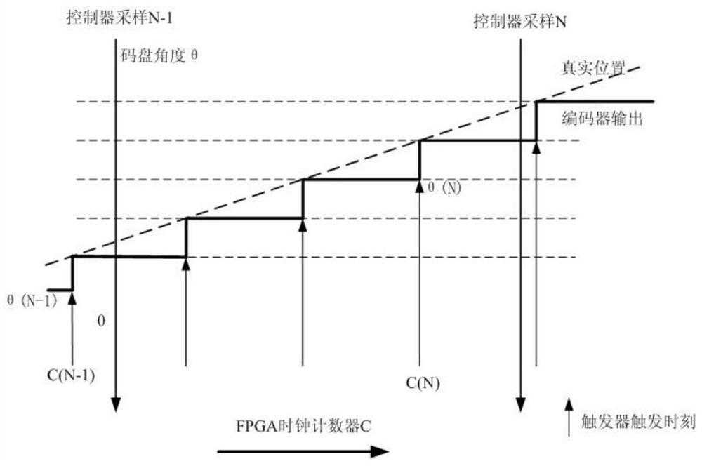
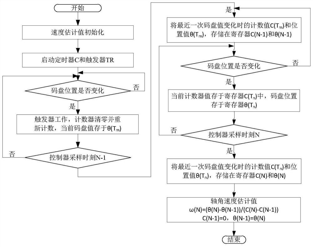
[0020] The speed estimation method based on position interpolation, through interpolation within the interval of the speed measurement timer, accurately captures the moment when the minimum resolution bit of the code disc changes, and uses the difference formula of enhanced speed estimation to obtain the shaft angular speed with higher speed resolution and phase lag, Improve the tracking performance of the speed loop, thereby improving the tracking accuracy of the optical axis of the optically stabilized platform. It mainly involves three aspects:

[0021] 1) Capture the moment of position change. The FPGA is used to trigger the signal edge of the position change, the counter of the FPGA is recorded as zero, and counting is started. The counting interval can be set according to the range of the speed to be estimated, generally set at the level of hundreds of ns to μs.

[0022] 2) Time interval calculation. When the signal edge of the second position change occurs, the FPGA c...


PUM


Abstract

The invention relates to a position interpolation-based axial angular speed estimation method. According to the method, on the basis of encoding disk T method speed measurement, a time point when theminimum resolution bit of an encoding disk changes is accurately obtained; an axial angular speed is obtained through an enhanced speed estimation formula; and therefore, phase lag can be reduced, speed loop gain is improved, and the disturbance suppression capability and following accuracy of a stabilization platform can be improved. The method has a broad application prospect.

Description

technical field [0001] The invention relates to a method for estimating shaft angular velocity based on position interpolation, and belongs to the technical field of photoelectric detection. Background technique [0002] The airborne photoelectric stabilization platform is mainly used to isolate external disturbances and follow the command angle to achieve target capture and precise tracking. However, in the airborne environment, the following of the command angle is affected by factors such as aircraft attitude changes, target maneuvers, and aircraft vibrations. The boresight cannot track the target movement according to the expected accuracy. Therefore, the frequency response and tracking of the speed loop must be improved. Accuracy, thereby improving the anti-interference ability and target tracking accuracy of the optoelectronic stabilized platform. [0003] The most important condition for the airborne optoelectronic platform to achieve disturbance isolation and comman...

Claims


Application Information

Patent Timeline
Patent Type & Authority Patents(China)
IPC IPC(8): G01P3/00G01P3/36
CPCG01P3/00G01P3/36
Inventor 高军科韩文斌李莉张红刚
Owner LUOYANG INST OF ELECTRO OPTICAL EQUIP OF AVIC
Why Eureka
Try Eureka