
Engine misfire fault diagnosis method based on mass center generalized force recognition

A technology for engine and fault judgment, applied in internal combustion engine testing and other directions, can solve problems such as low precision, lack of universality, poor versatility, etc., and achieve the effect of high sensitivity

Inactive Publication Date: 2019-01-25
SHANDONG JIAOTONG UNIV
View PDF4 Cites 4 Cited by
  • Summary
  • Abstract
  • Description
  • Claims
  • Application Information

AI Technical Summary

Problems solved by technology

[0004] However, as a fault diagnosis method based on response signals, it is greatly affected by external conditions such as engine structure, environment, temperature, and the installation position of sensors. It can only be effective for specific engines, a small number of components, and fault types. universality
In 2013, Wang Guobiao pointed out that although single-fault diagnosis is usually easy to implement, when it is popularized and used, its accuracy is not high, its generalization ability is not strong, and its versatility is poor, which restricts its application in engineering.
In addition, it was suggested that the cylinder pressure signal can be used for valve clearance monitoring and fault diagnosis. The scale signal decomposed from the binary wavelet of the cylinder pressure signal contains a large amount of state information of the valve clearance. There are certain difficulties in this aspect, and for some mechanical failures not related to combustion, the type and location of the failure cannot be determined from the pressure signal in the cylinder

Method used


Image

  • Engine misfire fault diagnosis method based on mass center generalized force recognition
  • Engine misfire fault diagnosis method based on mass center generalized force recognition
  • Engine misfire fault diagnosis method based on mass center generalized force recognition

Examples


Embodiment Construction

[0019] Below in conjunction with embodiment the present invention is further described, and the content of embodiment is not as the limitation to protection scope of the present invention.

[0020] The premise of realizing engine running state monitoring, fault prediction and diagnosis is to select reasonable monitoring and analysis objects in order to accurately extract fault symptoms from engine running dynamic signals, so the monitoring objects must have high sensitivity, stability, Uniqueness and convenience. When a fault occurs, the characteristics of the monitoring object can change accordingly; changes in the environment and working conditions will not affect the change of its characteristics; corresponding to different faults, the monitoring object has different characteristics; the monitoring object should also be easy to obtain and can be used in Tested directly under engine operating conditions. For engine condition monitoring, the test and characteristic changes o...


PUM


Abstract

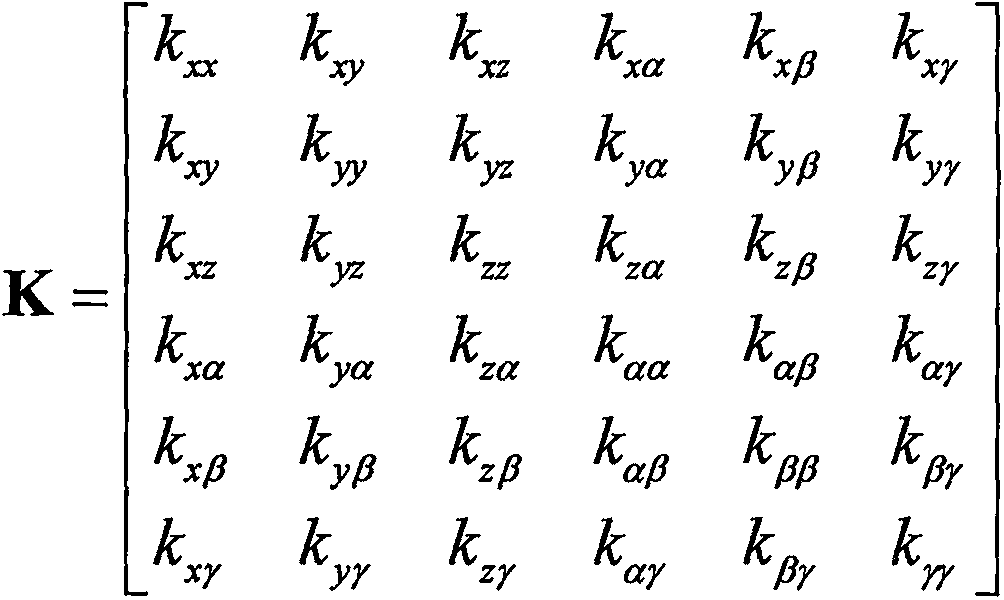
The invention relates to an engine misfire fault judgment method based on mass center generalized force recognition. The method comprises the following steps of (1), obtaining the coordinates of a suspension system of an engine, the inertia parameters of the engine, the dynamic stiffness of the main shafts of the suspension system, and the included angles between the main shafts and the axes of afixed coordinate system; (2), testing a vibration acceleration response signal under a steady-state working condition of the engine; (3), extracting the amplitudes, phases and frequencies of the harmonic components of the vibration acceleration response signal of the suspension system by means of a ratio correction method of a discrete spectrum correction technology added with a Hanning window; and (4), recognizing the mass center generalized force of the engine according to the following formula as shown in the description by utilizing the results in the steps (1) and (3), analyzing the characteristics of a vibration signal of the mass center generalized force of the engine, and distinguishing engine misfire faults. According to the method, the sensitivity of misfire fault judgment is high.

Description

technical field [0001] The invention belongs to the technical field of mechanical equipment fault judgment and signal processing, and relates to a method for judging an engine misfire fault, in particular to a method for judging an engine misfire fault based on centroid generalized force recognition. Background technique [0002] The vibration analysis method is to measure the vibration signal of the cylinder head or cylinder block during the working process of the engine, analyze and process it to extract the fault characteristics, obtain the characteristic parameters of the vibration signal, and judge the fault of the engine according to the change rule of the characteristic parameters. [0003] In 1996, on the basis of experiments, F.Gu and A.D.Ball of the University of Manchester in the United Kingdom concluded that the vibration of the diesel injector was mainly caused by the impact of the needle valve opening and seating and high-pressure fuel flow. The vibration senso...

Claims


Application Information

Patent Timeline
IPC IPC(8): G01M15/11
CPCG01M15/11
Inventor 徐传燕乔意徐海云曹凤萍富文军杜灿谊张绍辉
Owner SHANDONG JIAOTONG UNIV
Learn More