
Stretching clamping type engine oil pan oil drainage blocking system and method for applying same

An engine oil and oil pan technology, applied in the directions of oil pan, engine components, machine/engine, etc., can solve the problem of torque control, etc., and achieve the effects of easy operation, firm connection and easy operation

Pending Publication Date: 2019-01-25
DONGFENG COMML VEHICLE CO LTD
View PDF9 Cites 0 Cited by
  • Summary
  • Abstract
  • Description
  • Claims
  • Application Information

AI Technical Summary

Problems solved by technology

[0006] The purpose of the present invention is to overcome the defects and problems existing in the prior art that threaded connections must be controlled by torque, and to provide a stretching and clamping engine oil pan oil drain that does not use threaded connections and does not require torque control Clogging system and method of use

Method used


Image

  • Stretching clamping type engine oil pan oil drainage blocking system and method for applying same
  • Stretching clamping type engine oil pan oil drainage blocking system and method for applying same
  • Stretching clamping type engine oil pan oil drainage blocking system and method for applying same

Examples


Embodiment 1

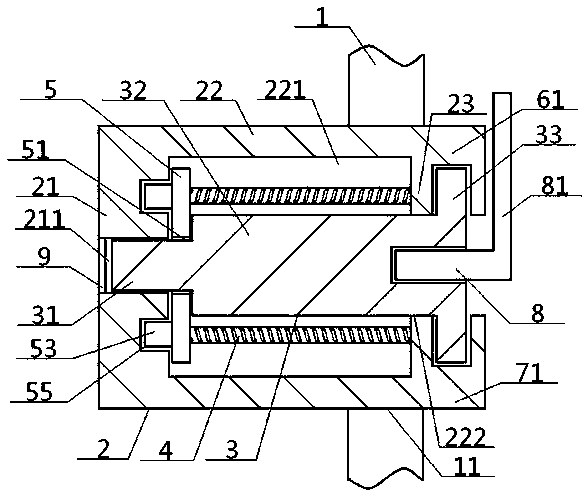
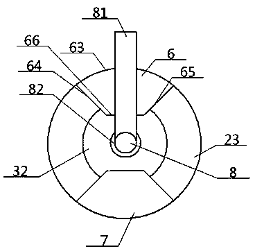
[0057] see Figure 1 to Figure 5 , a stretching clamping type engine oil pan oil drain plugging system, comprising a fixed seat 2 inside the shell and a plugging member 3 outside the shell, the outer wall of the fixed seat 2 inside the shell and the oil drain hole 11 in the oil pan 1 The inner walls are connected, and an insertion cavity 24 is opened inside the fixed seat 2 inside the shell, and the inserted cavity 24 is inserted into and matched with the inserting column 34 in the plugging member 3 outside the shell; the fixed seat 2 in the shell includes fixed front columns connected in sequence Body 21, fixed middle cylinder 22, and fixed rear cylinder 23. The fixed front cylinder 21 and fixed middle cylinder 22 are all located in the oil pan 1, and the fixed rear cylinder 23 is located outside the oil pan 1. There is a front column cavity 211 inside the column body 21, the outer wall of the fixed center column body 22 is connected with the inner wall of the oil discharge h...

Embodiment 2

[0062] Basic content is the same as embodiment 1, the difference is:

[0063] The outer surface of the piston sleeve 5 is provided with an upper guide column 52 and a lower guide column 53. The upper guide column 52 and the lower guide column 53 are vertically symmetrical with the central axis of the piston sleeve 5 as the line of symmetry. The upper guide column 52, The lower guide post 53 is respectively inserted into the upper guide hole 54 and the lower guide hole 55 provided in the fixed front column body 21 , and the upper guide post 52 and the lower guide post 53 are both shorter than the front insert post 31 .

Embodiment 3

[0065] Basic content is the same as embodiment 1, the difference is:

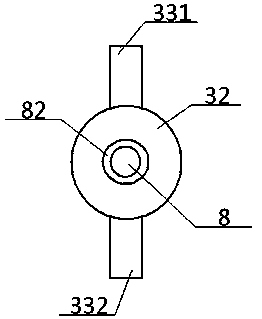
[0066] Described rear clamping body 33 comprises upper clamping block 331, lower clamping block 332, and described upper clamping block 331, lower clamping block 332 are respectively connected with the top, the bottom of middle inserting post 32 rear ends, upper clamping block 331, lower clamping block The outer surfaces of 332 are all flush with the outer surfaces of the middle post 32 rear ends, and the upper block 331 and the lower block 332 are point-symmetrical with the center of the center of the middle post 32 rear ends as the symmetrical point. The upper block 331 and the lower block The width of 332 is less than the radius of the rear end of the middle post 32; the central part of the fixed back post 23 is provided with a middle back hole 222, and the top of the outer side of the fixed back post 23 is vertically connected with one end of the upper middle connecting block 61, The other end of the up...


PUM


Abstract

The invention discloses a stretching clamping type engine oil pan oil drainage blocking system which comprises an inner fixing seat, an outer blocking component and expansion springs. The inner fixingseat comprises a fixing front column, a fixing middle column and a fixing rear column, the outer blocking component comprises a front insertion column, a middle insertion column and a rear clamp body, the front insertion column and the middle insertion column are matched with inner cavities of the fixing front column and the fixing middle column in an insertion manner, the middle insertion columnand the expansion springs which are arranged in the fixing middle column can be driven by one another via a piston sleeve, the fixing rear column, an upper arc plate and a lower arc plate are clampedto form an upper clamp groove and a lower clamp groove, the upper arc plate and the lower arc plate are connected onto the fixing rear column, the rear clamp body comprises an upper clamp block and alower clamp block, the upper clamp block and the lower clamp block which are connected with the rear end of the middle insertion column are correspondingly clamped with the upper clamp groove and thelower clamp groove, and a transparent observation block is embedded in a front column cavity and is arranged in a position between the front end of the front insertion column and the outer side surface of the fixing front column. The stretching clamping type engine oil pan oil drainage blocking system in the design has the advantages that threaded connection, torque control or optional assembling / detaching tools can be omitted, and the stretching clamping type engine oil pan oil drainage blocking system is easy to operate and high in controllability.

Description

technical field [0001] The invention relates to an oil drain screw plug structure of an engine oil pan, which belongs to the field of engines, in particular to a stretching and locking type engine oil pan oil drain plugging system and a method of use thereof, which are particularly suitable for avoiding plugging and dismantling of threaded connections mode without torque control. Background technique [0002] When the engine reaches the maintenance mileage, it is necessary to replace the oil in the oil pan. Use a wrench to unscrew and remove the oil drain plug on the oil pan to release the internal oil, then tighten the oil drain plug and re-inject new oil. At present, the oil drain plugs of engines on the market are all connected with the oil drain plug seats on the oil pan in a threaded form. For aluminum alloy and plastic oil pans, their strength is lower than that of steel stamped oil pans. It often happens that users in the market do not follow the specified torque whe...

Claims


Application Information

Patent Timeline
Patent Type & Authority Applications(China)
IPC IPC(8): F01M11/00F01M11/04F01M11/10
CPCF01M11/00F01M11/0004F01M11/0408F01M11/10F01M2011/0416
Inventor 郑锐周一欣汤超赵月
Owner DONGFENG COMML VEHICLE CO LTD
Learn More