


Quick Research
Generate reliable direction feasibility study reports for your R&D in just a few steps.

Technical Q&A
Discover and master advanced knowledge NOW. Basics, ideas, possibilities, all at once.

Find Solutions
As an expert in R&D theories, this can generate solutions to your technical problems instantly.

Evaluate Feasibility
Analyze your overall solution with one click, know your potential R&D risks in advance.

Monitor Landscape
Get weekly tech updates, stay abreast of the latest tech innovations and key insights.
A coaxial wing folding mechanism
A wing folding mechanism and wing technology are applied in the field of aviation unmanned aerial vehicles, which can solve the problems of inaccurate expansion angle of the wings, unstable locking state of the wings, etc., and achieve reliable deployment, small space occupied by the body, and convenience. The effect of storage and transportation
- Summary
- Abstract
- Description
- Claims
- Application Information
AI Technical Summary
Problems solved by technology
Method used
Image

Examples
Embodiment Construction
[0036] The present invention will be described in detail below in conjunction with the accompanying drawings and examples.
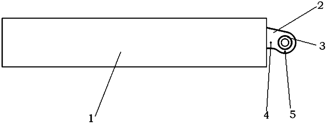
[0037] Such as figure 1 As shown, the integrated wing includes the wing main body 1 and the wing root joint 2. The circular part of the joint plate is the bearing 3. At the same time, there are two holes on the root plate, which are respectively the spring fixing hole 4 and the spring pin locking hole 5. . The two wings are installed on the same shaft, and are deployed by torsion springs, and locked in place by spring pins.
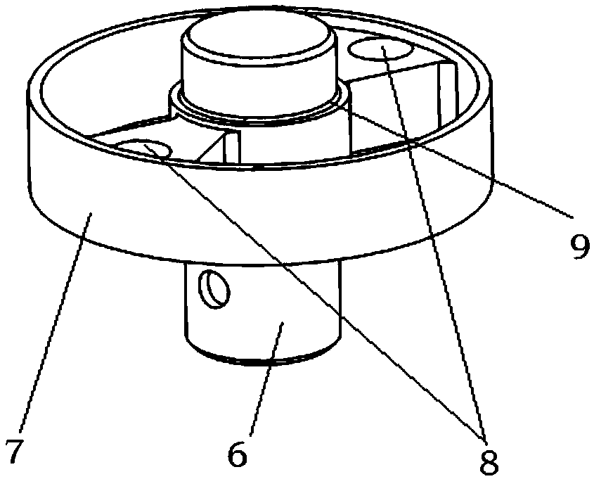
[0038] Such as figure 2 As shown, the rotating shaft includes a central shaft 6 for connecting and fixing with the fuselage, and an outer circular surface 7 for maintaining the stable contraction of the torsion spring, and a mounting hole 8 for a spring pin is arranged between the outer circular surface and the central shaft; The bearings of the two wing root joints are respectively fixedly connected with the central shaft on th...
PUM
 Abstract
Description
Claims
Application Information
 - R&D Engineer
- R&D Manager
- IP Professional
- Industry Leading Data Capabilities
- Powerful AI technology
- Patent DNA Extraction
Browse by: Latest US Patents, China's latest patents, Technical Efficacy Thesaurus, Application Domain, Technology Topic, Popular Technical Reports.
© 2024 PatSnap. All rights reserved.Legal|Privacy policy|Modern Slavery Act Transparency Statement|Sitemap|About US| Contact US: help@patsnap.com