


Quick Research
Generate reliable direction feasibility study reports for your R&D in just a few steps.

Technical Q&A
Discover and master advanced knowledge NOW. Basics, ideas, possibilities, all at once.

Find Solutions
As an expert in R&D theories, this can generate solutions to your technical problems instantly.

Evaluate Feasibility
Analyze your overall solution with one click, know your potential R&D risks in advance.

Monitor Landscape
Get weekly tech updates, stay abreast of the latest tech innovations and key insights.
Pouring sand mould of arc needles for pasture collection machinery and pouring method
A pouring method and arc-shaped needle technology, applied in the direction of casting mold, core, casting mold composition, etc., can solve the problems of unreliable sand shooting, large sand mold size, poor casting molding, etc., to improve pouring efficiency and flow path The effect of shortening and reducing the amount of sand used
- Summary
- Abstract
- Description
- Claims
- Application Information
AI Technical Summary
Problems solved by technology
Method used
Image


Examples
Embodiment 1
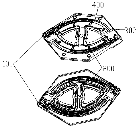
[0051] Refer to attached Figure 5-11 As shown, a casting sand mold of an arc-shaped needle for pasture collection machinery in this embodiment includes an upper shell 1, a lower shell 2, and a core assembly 3. Specifically, due to the change in the structure of the arc-shaped needle, the core Component 3 is used to supplementaryly form a certain part in the cavity that cannot be formed in the cavity. See attached Figure 6-7 It can be seen that, specifically, the upper casing 1 in this embodiment has an arc structure, and the arc structure is bent downward. Of course, downward bending is relative, and it can also be bent upward. According to the arc needle The degree of curvature determines the degree of curvature of the shell. In this embodiment, a first sprue 4 is provided in the middle of the arc structure, the first sprue 4 runs through the upper and lower ends of the upper shell 1, and the first sprue 4 is connected to the pouring cup for storing the pouring liquid. c...
Embodiment 2
[0060] As a further improvement of the above embodiment, in this embodiment, refer to the attached Figure 8-9 As shown, the cavity 6 is formed by the lower casing 2, specifically, an arc-shaped runner 9 is provided along the arc direction of the lower casing 2, and the runner 9 and the second sprue 5 communicate with each other, on both sides of the runner 9, there are cavity groups with the same structure respectively, specifically, each cavity group includes a plurality of cavity 6 parallel to the arc; each cavity 6 is connected to the horizontal The runners 9 communicate with each other. That is to say, the pouring liquid passes through the runner 9 and flows into the cavity groups on both sides at the same time, so that two cavity groups can be poured at the same time, and each cavity group can contain several cavities 6, so that multiple cavity groups can be poured at the same time. casting.
[0061] Preferably, in summary of this embodiment, each cavity group includes...
Embodiment 3
[0073] As a further improvement of Embodiments 1 and 2, the arc-shaped needle in this embodiment is an arc-shaped structure, and the two sides of the arc are respectively provided with pinholes, and the arc-shaped sides are provided with an arc-shaped guide rope groove structure. , in order to match the structure of the arc needle, refer to the attached Figure 10 As shown, the core assembly 3 includes a first core 301, a second core 302 and a third core 303. When installed, the first core 301 is placed at one end of the arc-shaped cavity 6 to form an arc A pinhole of the needle; the second core 302 is connected with the third core 303 to form an arc-shaped core, which is placed in the cavity 6, specifically placed near the side of the cavity 6, and the arc-shaped core will not be cast during casting. The core, and then can form the guide rope groove structure of the side of the arc needle; the second core 302 end is provided with columnar protrusions, and the columnar protrus...
PUM
| Property | Measurement | Unit |
|---|---|---|
| thickness | aaaaa | aaaaa |
| height | aaaaa | aaaaa |
| thickness | aaaaa | aaaaa |
Abstract
Description
Claims
Application Information
 - R&D Engineer
- R&D Manager
- IP Professional
- Industry Leading Data Capabilities
- Powerful AI technology
- Patent DNA Extraction
Browse by: Latest US Patents, China's latest patents, Technical Efficacy Thesaurus, Application Domain, Technology Topic, Popular Technical Reports.
© 2024 PatSnap. All rights reserved.Legal|Privacy policy|Modern Slavery Act Transparency Statement|Sitemap|About US| Contact US: help@patsnap.com