
Rod and wire online head and tail shearing system

A rod and wire, head and tail technology, applied in the field of rod and wire online head and tail shearing system, can solve problems such as breaking and accumulation

Pending Publication Date: 2019-01-25
汉威广园(广州)机械设备有限公司
View PDF0 Cites 0 Cited by
  • Summary
  • Abstract
  • Description
  • Claims
  • Application Information

AI Technical Summary

Problems solved by technology

[0005] In order to solve the above-mentioned technical problems, the present invention provides an online head-to-tail shearing system for rods and wires. By setting high-speed cutting shears, the shearing system solves the problems of accumulation and breaking of rods and wires when changing lanes, fundamentally It avoids the occurrence of shearing accidents and meets the requirements of high-speed rolling at the same time

Method used


Image

  • Rod and wire online head and tail shearing system
  • Rod and wire online head and tail shearing system
  • Rod and wire online head and tail shearing system

Examples


Embodiment 1

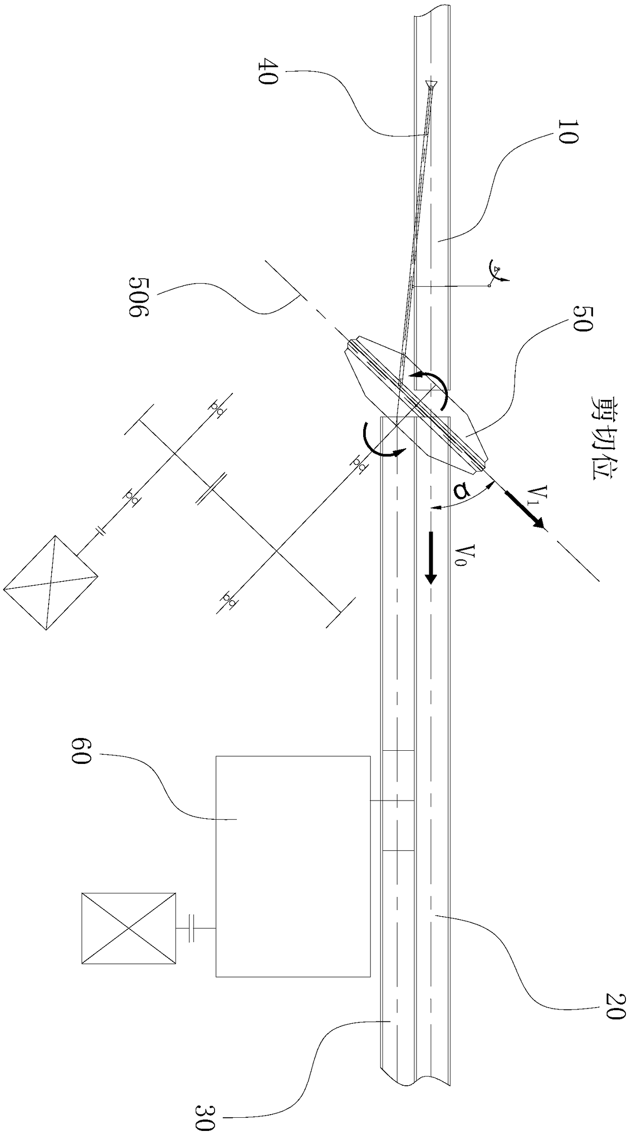
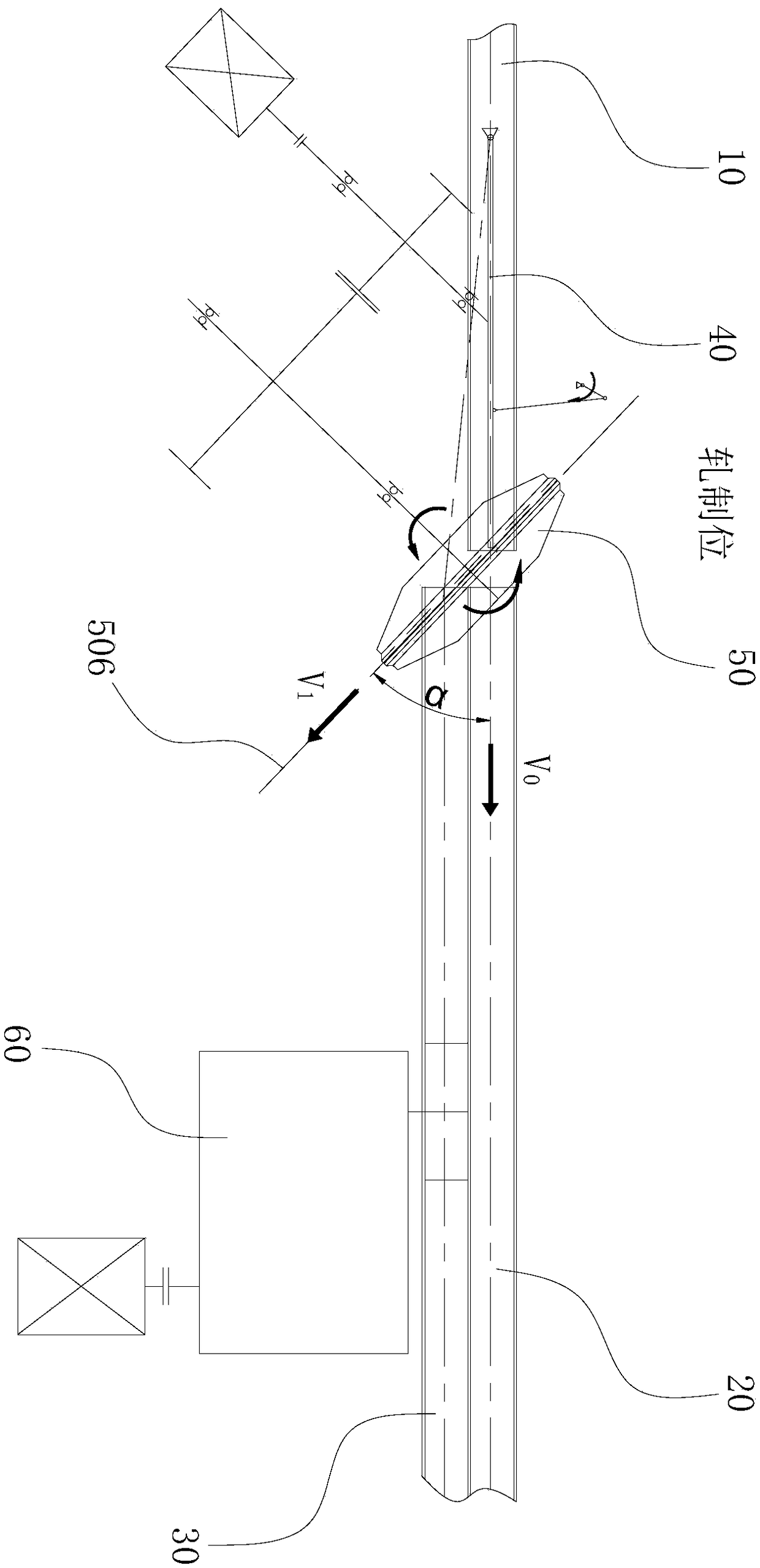
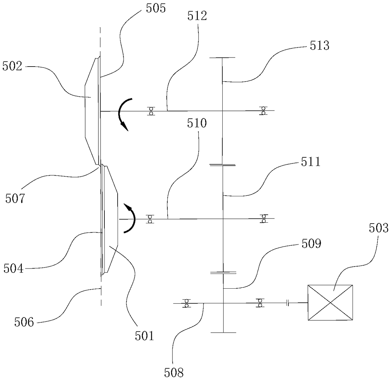
[0033] Such as Figure 1 to Figure 2As shown, the embodiment of the present invention provides an online head and tail shearing system for rods and wires, which mainly includes a front channel 10, a rolling channel 20, a shearing channel 30, a switch 40, a high-speed cutting shear 50 and a cutting head and tail fly Cut 60. The rolling channel 20 and the shearing channel 30 are arranged side by side in the horizontal direction, and the front channel 10 is arranged upstream of the rolling channel 20 and the shearing channel 30; the switch 40 is arranged on the front channel 10 and can be rolled The channel 20 and the shearing channel 30 swing back and forth to realize the channel changing function of the rod and wire between the rolling channel 20 and the shearing channel 30. The switch 40 can be driven by a servo motor, a servo cylinder or an electromagnetic induction device; The cutting shears 50 are arranged between the front passage 10 and the rolling passage 20 and the she...

Embodiment 2

[0045] Such as Figure 5 to Figure 6 As shown, the only difference between this embodiment and Embodiment 1 is that the first synchronous gear 511 and the second synchronous gear 513 are respectively located on both sides of the shear plane 506, and there are two input gears 509, and the two input gears 509 Respectively recorded as the first input gear 509a and the second input gear 509b, the first synchronous gear 511 meshes with the first input gear 509a, and the second synchronous gear 513 and the second input gear 509b are simultaneously connected with the transmission between the two Gears 514 mesh. Based on this, the motor 503 first drives the first synchronous gear 511 and the transmission gear 514 to rotate in the same direction through the first input gear 509a and the second input gear 509b respectively, and the transmission gear 514 drives the second synchronous gear 513 to rotate in the opposite direction. Realize the opposite rotation of the first synchronous gea...


PUM


Abstract

The invention provides a rod and wire online head and tail shearing system. Compared with the prior art, on one hand, the rod and wire online head and tail shearing system is provided with high-speedbreaking shears, the influence of the swing speed of trip switches on shearing operation is removed, the problems of stacking, breaking and the like caused by channel change of rods and wires are solved, so that shearing accidents are fundamentally avoided, the shearing speed and the rolling speed are closely linked by the high-speed breaking shears, so that limit in further increase of the rolling speed of the rods and wires is broken, the rod and wire online head and tail shearing system can meet high-speed rolling requirements, on the other hand, the high-speed breaking shears can rotate, the positions of the high-speed breaking shears are in one-to-one correspondence to those of the trip switches, so that the rod and wire online head and tail shearing system is only provided with a shearing channel, the functions of shearing heads, shearing tails, breaking and the like can be achieved, the structure of the whole shearing system is simplified, space size is reduced, and operating cost is more reduced.

Description

technical field [0001] The invention relates to the technical field of rod and wire shearing, in particular to an online head and tail shearing system for rods and wires. Background technique [0002] Flying shears are commonly used equipment in steel bar and wire production lines. At the same time, if an accident occurs during production, the flying shears can also achieve the function of breaking to ensure production safety. Traditional flying shears include crank-type flying shears, rotary flying shears or crank-rotary combined flying shears, etc. Their common feature is that the shearing plane is perpendicular to the traveling direction of the rod and wire. [0003] Flying shears are generally installed on the shearing channel arranged side by side with the rolling channel, and the moving rods and wires are switched between the two channels through the switch: when the flying shears complete the shearing process on the rods and wires, the switch immediately The swing g...

Claims


Application Information

Patent Timeline
Patent Type & Authority Applications(China)
IPC IPC(8): B21B15/00B21F11/00
CPCB21B15/0007B21F11/00B21B2015/0014
Inventor 朱建伟
Owner 汉威广园(广州)机械设备有限公司
Learn More