
Peak-shaving power supply control method and device

A technology for power supply control and power generation devices, applied in circuit devices, wind power generation, electrical components, etc., can solve problems such as wind power generation devices cannot run stably, and achieve the effect of stable and stable power supply

Active Publication Date: 2019-01-22
NANJING CHSCOM ELECTRICAL TECH CO LTD +3
View PDF12 Cites 0 Cited by
  • Summary
  • Abstract
  • Description
  • Claims
  • Application Information

AI Technical Summary

Problems solved by technology

[0004] In view of this, the object of the present invention is to provide a peak-shaving power supply control method to solve the problem that the wind power generation device cannot operate stably in the prior art
[0005] Another object of the present invention is to provide a peak-shaving power supply control device to solve the problem that wind power generation devices cannot operate stably in the prior art

Method used


Image

  • Peak-shaving power supply control method and device
  • Peak-shaving power supply control method and device
  • Peak-shaving power supply control method and device

Examples


no. 1 example

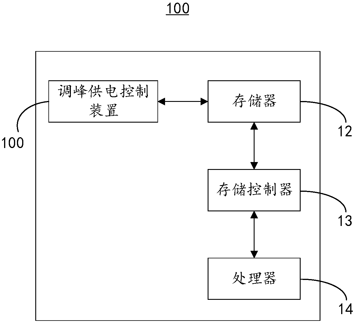
[0029] Such as figure 1 As shown, it is a schematic diagram of the functional modules of the server 10 provided by the present invention. The server 10 includes as figure 1 As shown, it is a schematic diagram of the functional modules of the server 10 provided by the present invention. The server 10 includes a peak-shaving power supply control device 100 , a memory 12 , a storage controller 13 and a processor 14 .

[0030] The components of the memory 12 , the storage controller 13 and the processor 14 are electrically connected to each other directly or indirectly to realize data transmission or interaction. For example, these components can be electrically connected to each other through one or more communication buses or signal lines. The peak shaving power supply control device 100 includes at least one software function module that can be stored in the memory 12 in the form of software or firmware (firmware) or solidified in the operating system (operating system, OS) ...

no. 2 example

[0073] see Figure 4 , provided by the preferred embodiment of the present invention figure 1 The schematic diagram of the functional units of the peak shaving power supply control device 100 is shown. It should be noted that the basic principles and technical effects of the peak-shaving power supply control device 100 provided in this embodiment are the same as those of the above-mentioned embodiments. For a brief description, reference may be made to the above-mentioned The corresponding content in the embodiment. The peak shaving power supply control device 100 includes:

[0074] The time acquisition unit 110 is configured to acquire the current time.

[0075] It can be understood that step S101 can be executed by the time acquiring unit 110 .

[0076] The period determination unit is configured to determine the power supply period according to the corresponding relationship between the current time and the preset power supply period.

[0077] It can be understood that...


PUM


Abstract

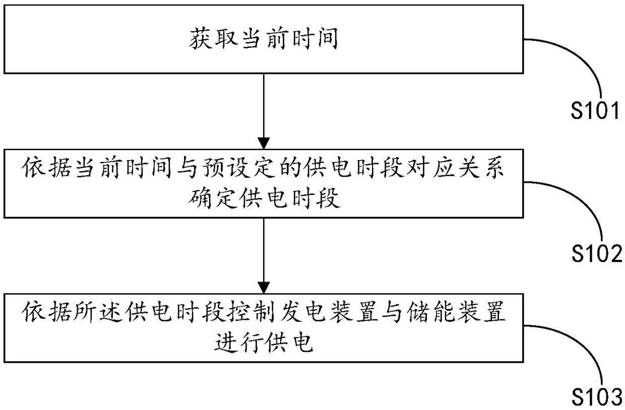
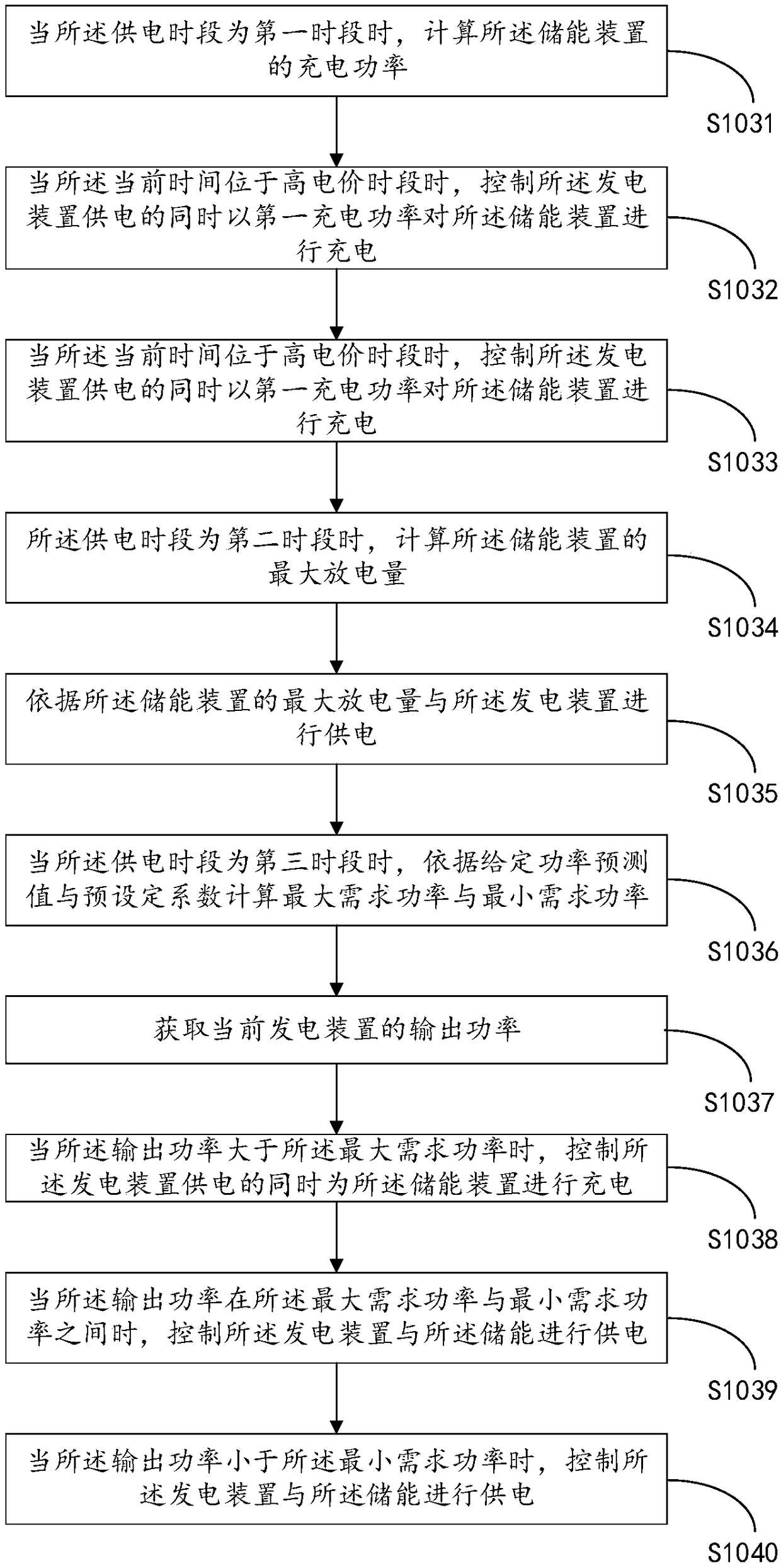
The invention provides a peak-shaving power supply control method and device, which relate to the technical field of power supply. By acquiring the current time, the power supply period is determinedaccording to the corresponding relationship between the current time and the preset power supply period, wherein the power supply period comprises a first period, a second period and a third period, and finally the power generation device and the energy storage device are controlled to supply power according to the power supply period. The peak-shaving power supply control method and device provided by the invention have the effect of more stable power supply.

Description

technical field [0001] The present invention relates to the technical field of power supply, in particular to a method and device for controlling peak-shaving power supply. Background technique [0002] Wind energy is a new type of energy. Compared with traditional energy sources, it has the advantages of being renewable, low-cost, and free of pollutants and carbon emissions. At the same time, its large-scale and commercial development prospects and clean utilization methods make the power generation of wind energy resources , transmission and use related technologies have become the current research hotspots in the industry. However, due to the randomness and uncertainty of wind energy, as well as the peak and low peak periods of electricity consumption when users use electricity, it will have an impact on the stable operation of wind power generation devices. [0003] In view of this, how to solve the above problems is the focus of attention of those skilled in the art. ...

Claims


Application Information

Patent Timeline
Patent Type & Authority Applications(China)
IPC IPC(8): H02J3/38H02J3/32
CPCH02J3/32H02J3/386Y02E10/76
Inventor 张莉汪成根雷震安德超王奎林文莉
Owner NANJING CHSCOM ELECTRICAL TECH CO LTD
Learn More