Municipal engineering pipe classifying and receiving equipment
A technology for engineering and pipe materials, which is applied in the field of pipe classification and receiving equipment for municipal engineering, can solve the problems of inability to solve pipes, the inability to adjust the width of the material guide plate of the material receiving device, and the inability to adjust the size of the upper and lower material openings of the material receiving device, etc., to achieve improvement The effect of work efficiency
- Summary
- Abstract
- Description
- Claims
- Application Information
AI Technical Summary
Problems solved by technology
Method used
Image
Examples
Embodiment 1
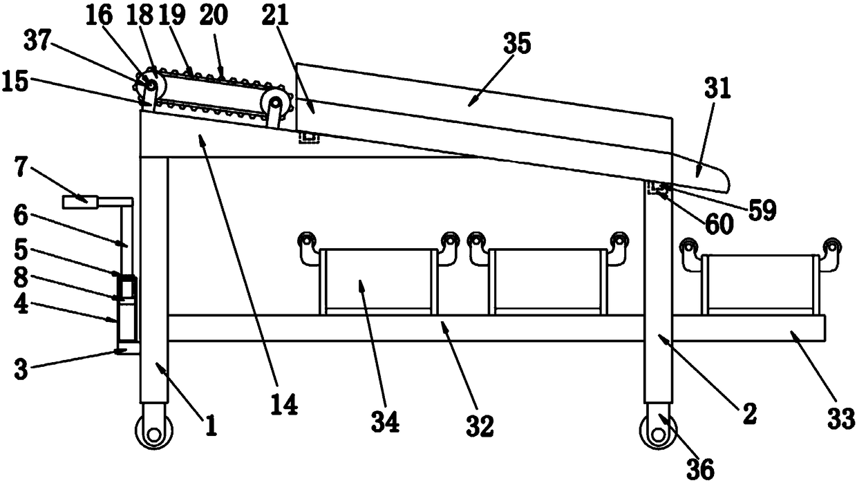
[0056] Embodiment one please refer to Figure 1-3 , a kind of equipment for sorting and receiving pipe materials for municipal engineering, comprising a support plate a1 and a support plate b2, characterized in that: the upper surface of the support plate a1 is welded with a support block 14, and the upper surface of the support block 14 is respectively connected to four The bottom ends of the four support rods 15 are fixedly connected, and the four support rods 15 are symmetrically arranged on the upper surface of the support block 14, and the opposite sides of the two support rods 15 are clamped with bearings a37, and the two bearings a37 Both are sleeved on the outer surface of the rotating shaft a16, and the outer surfaces of the two rotating shafts a16 are fixedly connected with a transmission wheel 18, and the two driving wheels 18 are connected through a transmission belt 19, and one end of the back of the rotating shaft a16 is connected to the drive motor 17 The output...
Embodiment 2
[0058] Embodiment 2 Please refer to figure 1 , 4 , 5, the side of the support plate a1 is welded with a fixed block 3, the upper surface of the fixed block 3 is fixedly installed with a fixed cylinder 4, the upper surface of the fixed cylinder 4 is clamped with a sliding sleeve 5, and the sliding sleeve 5 The inner wall of the fixed rod 6 is sleeved with a fixed rod 6, the top end of the fixed rod 6 is welded with a handle 7, the bottom end of the fixed rod 6 is fixedly connected with the upper surface of the limiting plate 8, and both sides of the limiting plate 8 are A groove a9 is provided, and springs 10 are fixedly installed on the inner walls of the two grooves a9, and the opposite ends of the two springs 10 are respectively fixedly connected to the opposite sides of the two connecting plates 11, and the two connecting plates 11 The opposite sides are respectively fixedly connected to the opposite sides of the two pressure blocks 12, and the two pressure blocks 12 respe...
Embodiment 3
[0060] Embodiment three please refer to Figure 6 A groove b23 is opened on the material guide plate 21 on the side of the material discharge port 22, and a movable plate 24 is arranged inside the groove b23. One side of the movable plate 24 is fixedly connected with the slider b41, and the slider b41 is slidably connected with the chute b42, and the chute b42 is opened on the material guide plate 21 on one side of the groove b23. A gap 25 is opened on one side of the material guide plate 21, and the movable plate 24 extends out of the material guide plate 21 through the gap 25, and is welded with a connecting block 26, and a bearing b38 is clamped on one side of the connecting block 26 , and the inner wall of the bearing b38 is sleeved with a rotating shaft b27, the rotating shaft b27 is fixedly connected with the threaded post 28, one end of the threaded post 28 is welded with a handle 43, and the outer surface of the threaded post 28 is threaded with a threaded cap 29 , th...
PUM
 Abstract
Description
Claims
Application Information
 - Generate Ideas
- Intellectual Property
- Life Sciences
- Materials
- Tech Scout
- Unparalleled Data Quality
- Higher Quality Content
- 60% Fewer Hallucinations
Browse by: Latest US Patents, China's latest patents, Technical Efficacy Thesaurus, Application Domain, Technology Topic, Popular Technical Reports.
© 2025 PatSnap. All rights reserved.Legal|Privacy policy|Modern Slavery Act Transparency Statement|Sitemap|About US| Contact US: help@patsnap.com


