Data transmission method, base station, and terminal
A data transmission method and base station technology, which are applied in connection management, wireless communication, electrical components, etc., can solve problems such as inability to effectively realize data forwarding, and achieve the effects of reducing network burden, delay, and signaling load.
- Summary
- Abstract
- Description
- Claims
- Application Information
AI Technical Summary
Problems solved by technology
Method used
Image
Examples
Embodiment 1
[0109] Embodiment 1: Base station configures DRX parameters and valid period
[0110] When the UE's downlink data arrives at the source base station, the source base station (anchor base station) can determine the number and interval of subsequent uplink and downlink data packets according to the UE's business type and business model, and can also refer to the UE's capability, moving speed and The DRX configuration of the UE in the idle state and the connected state is to configure a reasonable DRX configuration for the UE to monitor downlink data in the preset state (that is, the above-mentioned DRX parameters, the same below). At the same time, in order to save power, the source base station can also set a validity period for the DRX configuration in consideration of the time of data packet transmission. During the validity period, the UE adopts the DRX configuration of monitoring downlink data in the preset state configured by the source base station; , the DRX configuratio...
Embodiment 2
[0114] Embodiment 2: The base station configures DRX parameters and activates / deactivates DRX parameters
[0115] When the UE's downlink data arrives at the source base station, the source base station may inform the target base station to activate DRX configuration of the UE in the connected state.
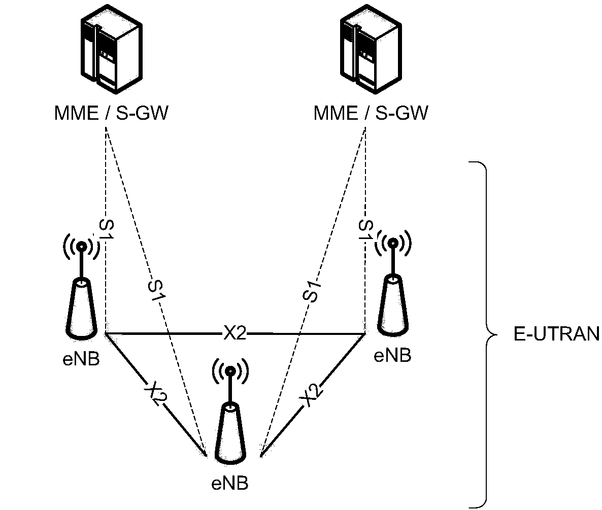
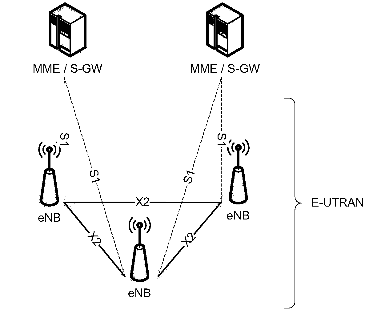
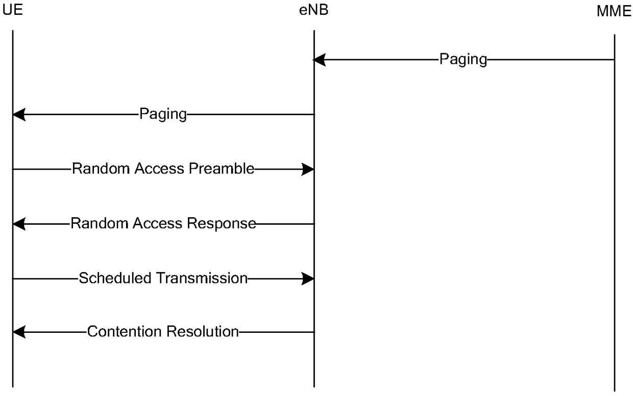
[0116] That is to say, when the downlink data of the UE arrives at the source base station, the source base station will page the UE within a certain range to notify the UE of the arrival of the downlink data. The source base station sends the paging message or downlink data packet to the target base station through an interface (for example, X2). In addition, the source base station will inform the target base station of the DRX configuration of the activated UE in the connected state through an interface (for example, X2), and at the same time, can also inform the target base station of the DRX configuration of the UE in the connected state. The interface message may be a pagi...
Embodiment 3
[0122] Embodiment 3: configuration of uplink resources
[0123] For the downlink data packets of the UE, the UE needs to perform uplink HARQ ACK / NACK feedback. However, in a default state, the UE has no uplink resources. Then, when the target base station is sending downlink data packets for the UE, it can allocate the PUCCH resource of the cell to the UE according to the service type and the load of the cell, and at the same time, can also indicate the validity period of the PUCCH resource (for example, the timer duration or times), and notify the UE in the paging message or PDCCH command or MAC CE.
[0124] After receiving the configuration of PUCCH resources, the UE will feed back uplink HARQ ACK / NACK according to the configured resources. If the base station configures the validity period, the UE will only feed back on the PUCCH resource within the validity period.
PUM
 Abstract
Description
Claims
Application Information
 - R&D Engineer
- R&D Manager
- IP Professional
- Industry Leading Data Capabilities
- Powerful AI technology
- Patent DNA Extraction
Browse by: Latest US Patents, China's latest patents, Technical Efficacy Thesaurus, Application Domain, Technology Topic, Popular Technical Reports.
© 2024 PatSnap. All rights reserved.Legal|Privacy policy|Modern Slavery Act Transparency Statement|Sitemap|About US| Contact US: help@patsnap.com


