Eureka AIR delivers breakthrough ideas for toughest innovation challenges, trusted by R&D personnel around the world.

A magnetic ring inductance processing device

A processing device and magnetic ring inductance technology, which is applied in coil manufacturing and other directions, can solve problems such as coil superposition, affect winding quality, side leakage, etc., achieve efficient and accurate winding, improve processing efficiency, and have high equipment linkage.

Inactive Publication Date: 2019-01-18
浙江长兴瑞和电子科技有限公司
View PDF1 Cites 2 Cited by
  • Summary
  • Abstract
  • Description
  • Claims
  • Application Information

AI Technical Summary

Problems solved by technology

[0003] The magnetic ring inductance processing device in the above-mentioned patent has the following disadvantages: the existing devices for winding the magnetic ring need to locate the magnetic ring, and at the same time, the density of the magnetic winding wire and the winding speed cannot be controlled, which will affect the winding speed. The quality of time, causing some coil superposition or side leakage phenomenon

Method used

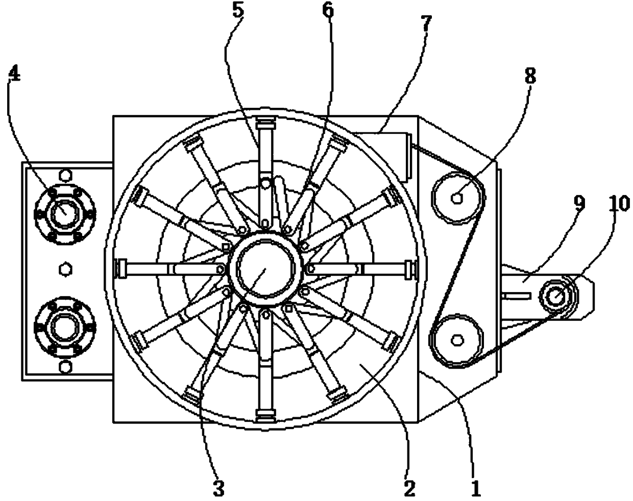
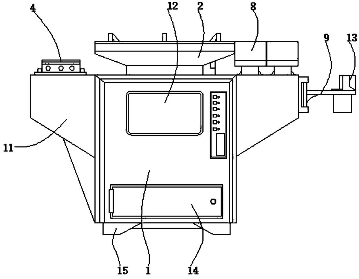
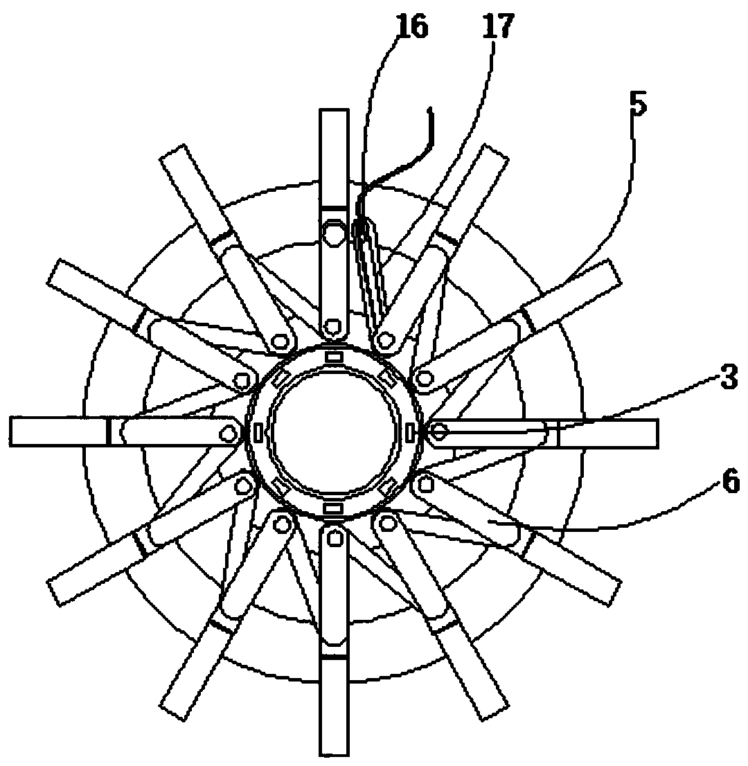

Image

  • A magnetic ring inductance processing device
  • A magnetic ring inductance processing device
  • A magnetic ring inductance processing device

Examples


Embodiment Construction

[0021] In describing the present invention, it should be understood that the terms "center", "longitudinal", "transverse", "length", "width", "thickness", "upper", "lower", "front", " Orientation indicated by rear, left, right, vertical, horizontal, top, bottom, inside, outside, clockwise, counterclockwise, etc. The positional relationship is based on the orientation or positional relationship shown in the drawings, and is only for the convenience of describing the present invention and simplifying the description, rather than indicating or implying that the referred device or element must have a specific orientation, be constructed and operated in a specific orientation, Therefore, it should not be construed as limiting the invention.

[0022] In addition, the terms "first" and "second" are used for descriptive purposes only, and cannot be interpreted as indicating or implying relative importance or implicitly specifying the quantity of indicated technical features. Thus, a ...


PUM


Abstract

A magnetic ring inductance processing device includes a cabinet, the four corners of the bottom outer wall of the cabinet body are fixedly provided with a base through bolts, the top inner wall of thecabinet body is provided with a servo motor, and the output shaft of the servo motor is connected with a processing table through a bearing, an electric push rod is fixed at the inner wall central axis of the processing table through bolts, and one end of the piston rod of the electric push rod is fixed with a spiral traction guide rail through a hinge, the two ends of the spiral traction guide rail are respectively provided with a magnetic ring and a magnetic buckle, a central magnetic rotating disk is arranged at the central axis of the top outer wall of the processing table, and a counterweight frame is welded on one outer wall of the cabinet body. As that electric push rod and the spiral traction guide rail of the invention cooperate with the upper magnetic buckle and the magnetic re,the electromagnetic traction track and the traction magnet blockcan move quickly by pushing and pulling, the coil is driven to be wound quickly, the magnetic ring is driven to be offset through the central magnetic rotating disk, the wound density is changed, and the magnetic ring is ensured to be wound efficiently and accurately.

Description

technical field [0001] The invention relates to the technical field of magnetic ring inductance processing, in particular to a magnetic ring inductive processing device. Background technique [0002] The magnetic ring is an anti-interference component commonly used in electronic circuits. It has a good suppression effect on high-frequency noise. The electromagnetic waves radiated and leaked by electronic equipment not only seriously interfere with the normal operation of other electronic equipment, but also cause equipment dysfunction and transmission errors. The electromagnetic interference (EMI) of the equipment is already a problem that must be considered. Absorbing magnetic rings, also known as ferrite magnetic rings, or magnetic rings for short, pass the entire bundle of cables through a ferrite magnetic ring to form a common mode choke According to the needs, the cable can also be wound several turns on the magnetic ring through the magnetic ring inductance processing ...

Claims


Application Information

Patent Timeline
Patent Type & Authority Applications(China)
IPC IPC(8): H01F41/08
CPCH01F41/08
Inventor 钱敏李东伟罗小庆
Owner 浙江长兴瑞和电子科技有限公司
Why Eureka
Eureka Blog
Learn More