Film rolling mechanism

A winding mechanism and film technology, applied in the direction of winding strip, thin material processing, transportation and packaging, etc., can solve the problems of low efficiency of winding roll replacement, affecting the efficiency of film winding, and troublesome operation. Meet the needs of film winding, improve efficiency and quality, and achieve efficient and accurate winding results

Active Publication Date: 2015-11-25
浙江耀阳新材料科技有限公司
View PDF8 Cites 4 Cited by
  • Summary
  • Abstract
  • Description
  • Claims
  • Application Information

AI Technical Summary

Problems solved by technology

During the production and processing of the existing film, the film needs to be rewound after gluing, drying and other operations according to the needs. The existing film rewinding device has a complex structure and troublesome operation. During the film rewinding process, the entire rewinding The winding mechanism is only equipped with one winding roller. After the winding roller finishes winding the film, another winding roller needs to be replaced manually so that the film can continue to be wound. Since the manual replacement of the winding roller takes a long time Long, the efficiency of rewinding roller replacement is low, and the entire film conveying device needs to be shut down, which affects the efficiency of film rewinding, increases the labor intensity of workers, and cannot meet the needs of production and use.

Method used


Image

  • Film rolling mechanism
  • Film rolling mechanism

Examples


Embodiment Construction

[0010] In order to further describe the present invention, a specific implementation of a film winding mechanism will be further described below in conjunction with the accompanying drawings. The following examples are explanations of the present invention and the present invention is not limited to the following examples.

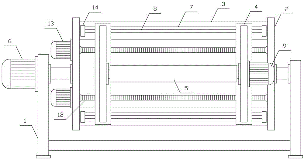
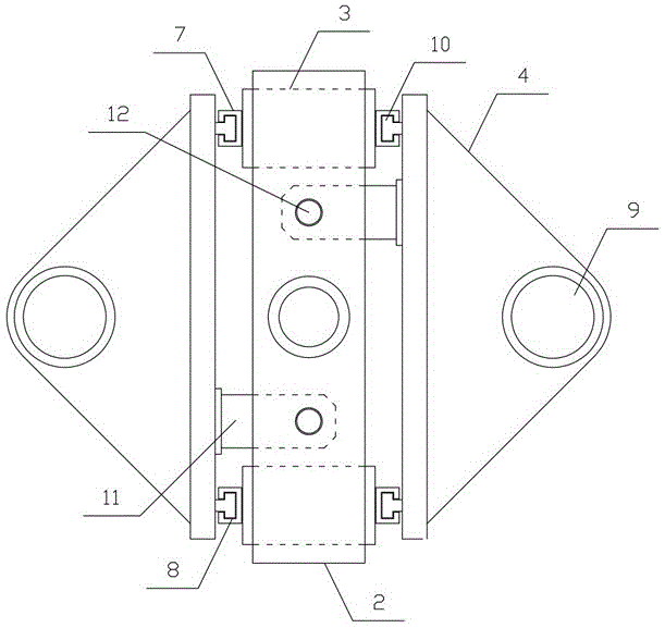
[0011] like figure 1 , figure 2 As shown, a film winding mechanism of the present invention includes a fixed support 1, a translation support 2, a translation support plate 3, a winding support 4 and a winding roller 5, and the translation support 2 is horizontally arranged on the upper side of the fixed support 1. The middle parts on both sides of the bracket 2 are respectively connected to the fixed bracket 1 in rotation, and a rotating motor 6 is horizontally arranged on one side of the fixed bracket 1, and the rotating motor 6 drives the translation bracket 2, and the translation support plates 3 are respectively horizontally arranged at both ends of ...


PUM


Abstract

The invention discloses a film rolling mechanism, and belongs to the field of film machining devices. The film rolling mechanism comprises a fixed support, a horizontal movement support, a horizontal movement supporting plate, rolling supports and a rolling roller. The middles of the two sides of the horizontal movement support are rotationally connected to the fixed support. A rotation motor drives the horizontal movement support. Horizontal movement guiding plates are horizontally arranged on the two sides of the horizontal movement supporting plate respectively. The rolling supports are arranged on the two sides of the horizontal movement support respectively. A rolling motor drives the rolling roller. The rolling supports can horizontally move along the horizontal movement guiding plates. Horizontal movement drive plates are horizontally arranged at the two ends of one sides of the rolling supports respectively. Two horizontal movement motors drive two horizontal movement lead screws respectively. The two horizontal movement lead screws are in horizontal threaded connection with the horizontal movement drive plates on one sides of the two rolling supports respectively. The film rolling mechanism is simple in structure and convenient to use, films can be continuously rolled, the film rolling efficiency and quality are improved, and the requirements for production and usage are met.

Description

technical field [0001] The invention belongs to the field of film processing machinery and equipment, and in particular relates to a film winding mechanism. Background technique [0002] At present, films are more and more widely used in our production and life. Films are generally made of polyvinyl chloride, polyethylene, polypropylene, polystyrene and other resins, used for packaging and as a coating layer , plastic packaging and plastic packaging products are taking an increasing share in the market, and have been widely used in food, medicine, chemical and other fields, among which food packaging accounts for the largest proportion, such as beverage packaging, quick-frozen food packaging, Cooked food packaging, fast food packaging, etc., have brought great convenience to people's lives. During the production and processing of the existing film, the film needs to be rewound after gluing, drying and other operations according to the needs. The existing film rewinding devi...

Claims


Application Information

Patent Timeline
IPC IPC(8): B65H18/10B65H19/22
CPCB65H18/10B65H19/22B65H2301/41445B65H2301/41818
Inventor 李云锋陈彬张涛李浩亮
Owner 浙江耀阳新材料科技有限公司
Why Eureka
Try Eureka