Network test system based on typical ghost imaging
A technology for network testing and ghost imaging, applied in the direction of measuring devices, measuring electrical variables, measuring resistance/reactance/impedance, etc., can solve the problems of changing the power of the electrical signal, affecting the imaging results, and the high price of the vector network analyzer. Reduce the number of inspections, good results, and the effect of reducing equipment costs
- Summary
- Abstract
- Description
- Claims
- Application Information
AI Technical Summary
Problems solved by technology
Method used
Image
Examples
Embodiment 1
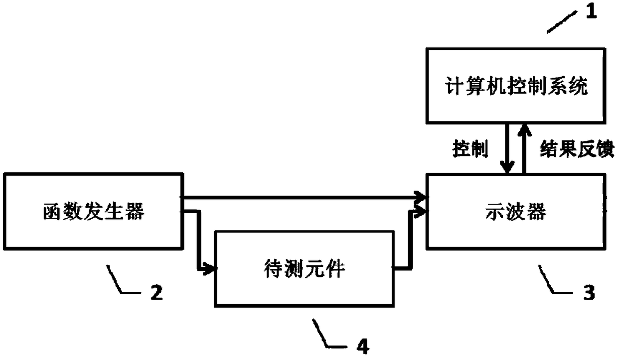
[0023] The schematic diagram of the network test system in this embodiment is as follows figure 1 As shown, the whole system includes a computer control system 1, to measure the frequency response of the component under test 4. Described oscilloscope 3 is connected with described computer control system 1, and an output end of described function generator 2 is directly connected with an input end of described oscilloscope 3, and another output end of described function generator 2 is connected with DUT 4, and the other input of the oscilloscope 3 is connected to the output of the DUT 4. At the beginning of the measurement, the oscilloscope 3 and the function generator 2 are initialized first. After the initialization is completed, the function generator 2 sends an uninterrupted random noise signal, the random noise signal passes through the component under test 4 all the way, and is finally received by the input terminal of the oscilloscope 3 and measures its waveform after p...
Embodiment 2
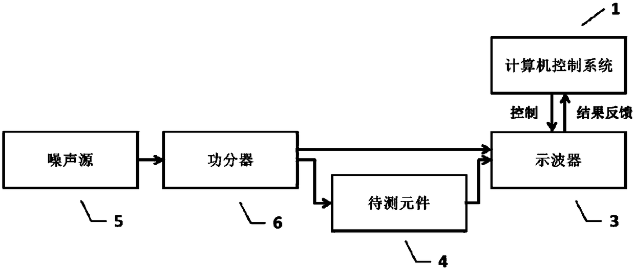
[0026] The schematic diagram of the network test system in this embodiment is as follows figure 2 As shown, the difference between the whole system and Embodiment 1 is that the noise source 5 and the power divider 6 connected in series are used instead of the function generator 2 to measure the frequency response of the component under test 4, and the rest are the same. The oscilloscope 3 is connected with the computer control system 1, the output end of the noise source 5 is connected with the input end of the power divider 6, one output end of the power divider is directly connected with an input end of the oscilloscope 3, and the other output end of the power divider 6 is One terminal is connected to the input terminal of the DUT 4, and the other input terminal of the oscilloscope 3 is connected to the output terminal of the DUT 4. At the beginning of the measurement, the oscilloscope 3 is first initialized. After the initialization is completed, an uninterrupted random n...
PUM
 Abstract
Description
Claims
Application Information
 - R&D
- Intellectual Property
- Life Sciences
- Materials
- Tech Scout
- Unparalleled Data Quality
- Higher Quality Content
- 60% Fewer Hallucinations
Browse by: Latest US Patents, China's latest patents, Technical Efficacy Thesaurus, Application Domain, Technology Topic, Popular Technical Reports.
© 2025 PatSnap. All rights reserved.Legal|Privacy policy|Modern Slavery Act Transparency Statement|Sitemap|About US| Contact US: help@patsnap.com


