Automatic detection device of tooth face precision of gear shaft

An automatic detection device and technology of detection device, applied in the direction of measuring device, testing of mechanical components, testing of machine/structural components, etc., can solve problems such as hidden safety hazards of installation accuracy, manual loading and unloading, and inaccurate detection.

Pending Publication Date: 2019-01-18
HARBIN UNIV OF SCI & TECH
View PDF0 Cites 1 Cited by
  • Summary
  • Abstract
  • Description
  • Claims
  • Application Information

AI Technical Summary

Problems solved by technology

[0003] The technical problem solved by the patent of the present invention is: in view of the lack of detection devices for gear shafts on the market and the defects of low automation in the detection devices, an automatic detection device for gear shafts has been invented; the invention can convert the gear shafts to be inspected It is automatically consigned from the designated storage location for inspection to the designated location, and the gear shaft to be inspected is installed by the manipulator to the inspection area of ​​the inspection device for inspection; this patent has invented an automatic inspection device for gear shafts, which solves the problem of manual loading and unloading during the inspection process , installation accuracy and potential safety hazards during installation, the inaccurate detection caused by installation errors during detection has been solved to the greatest extent

Method used


Image

  • Automatic detection device of tooth face precision of gear shaft
  • Automatic detection device of tooth face precision of gear shaft
  • Automatic detection device of tooth face precision of gear shaft

Examples


Embodiment Construction

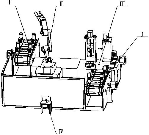
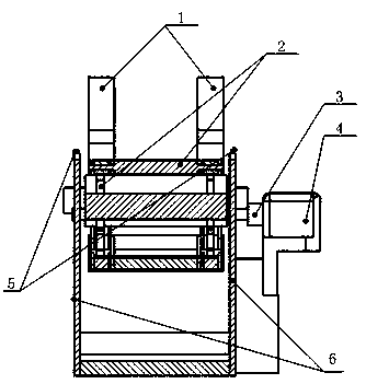
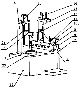
[0013]Place the gear shaft to be tested in the detection storage area, and consign the gear shaft from the detection storage area through the automatic transport device Ⅰ, where the motor (4) drives the gear in the sprocket (2) to rotate through the coupling (3) and then Make the chain of the sprocket (2) move, and the gear shaft consignment claw (1) installed on the chain consigns the gear shaft to the top of the positioning sensor (5) installed on the table body (6); the manipulator II passes through the big arm ( 48) Drive the middle arm (47) to move, then the small arm (46) drives the mechanical claw (44) on the basis of the movement of the middle arm (47) to pick up the gear shaft on the consignment claw (1), and through the rotating arm (45) Turn the gear shaft to a certain angle to ensure that the gear shaft reaches a vertical position, and install the gear shaft on the detection device III, and fix it by the lower center and the upper center (18) installed in the center...


PUM


Abstract

The invention relates to an automatic detection device of tooth face precision of a gear shaft. The device comprises an automatic transportation device I, a manipulator II, a detection device III anda display device IV, wherein the automatic transportation device comprises a motor, a coupler, chain wheels, transportation claws, location sensors and bench bodies; the detection device comprises a workbench, motors, couplers, a flat key, an air cylinder, a pressure sensor, a lever mechanism, displacement measurement rulers, measurement frames, screw rods, an upper tip upright, an upper tip, a lower tip, screw nuts, an X sliding table, a Y sliding table, a Z sliding table, a detection upright, a probe, a rotating table and springs; the display device comprises a display screen and a display table; the manipulator comprises a gripper, a rotating arm, a small arm, a middle arm, a large arm and a base; during detection, the transportation device transports the gear shaft to a position abovethe location sensor; the manipulator puts the gear shaft on the detection device; the detection device fixes the gear shaft through the upper tip and the lower tip; the probe scans a tooth profile; detection information is transmitted to the display screen; and the detected gear shaft is placed by the manipulator on the automatic transportation device to be transported to a temporary storage area.

Description

technical field [0001] The invention belongs to the field of automatic detection devices for gear shafts. Background technique [0002] The gear shaft and the connecting piece are driven together to transmit power and torque. The quality of the tooth surface accuracy of the gear shaft completely affects the quality of the transmitted power and torque; the device for measuring the accuracy of the tooth surface of the gear shaft was first introduced in China after being produced in Germany. However, the device for measuring the tooth surface accuracy of the gear shaft has not achieved the automatic function, and the gear shaft needs to be manually loaded on the detection device. Due to the relatively large uncontrollability of manual loading, it may be caused by manual reasons during the loading process. The collision between the detected part and the detection device will not only cause damage to the detected part, but also cause damage to the detection mechanism, which great...

Claims


Application Information

Patent Timeline
IPC IPC(8): G01M13/021G01M13/022
CPCG01M13/021G01M13/022
Inventor 孙永国李方乐陈哲
Owner HARBIN UNIV OF SCI & TECH
Why Eureka
Try Eureka