
Signal processing circuit and device for non-contact position sensor

A signal processing circuit, non-contact technology, applied in the direction of using electrical devices, electromagnetic measuring devices, measuring devices, etc., can solve the problems of rotor position information deviation, inaccurate detection results, loss of output signal of half-wave synchronous rectification, etc.

Active Publication Date: 2019-01-18
SHENZHEN FLYING FAIRY INTELLIGENT TECH CO LTD
View PDF6 Cites 1 Cited by
  • Summary
  • Abstract
  • Description
  • Claims
  • Application Information

AI Technical Summary

Problems solved by technology

[0006] The purpose of the present invention is to provide a signal processing circuit and device for a non-contact position sensor, aiming at solving the loss of the output signal of the half-wave synchronous rectification in the existing control technology for the non-contact position sensor. As a result, the obtained rotor position information is deviated, resulting in inaccurate detection results.

Method used


Image

  • Signal processing circuit and device for non-contact position sensor
  • Signal processing circuit and device for non-contact position sensor
  • Signal processing circuit and device for non-contact position sensor

Examples


Embodiment Construction

[0019] In order to make the object, technical solution and advantages of the present invention clearer, the present invention will be further described in detail below in conjunction with the accompanying drawings and embodiments. It should be understood that the specific embodiments described here are only used to explain the present invention, not to limit the present invention.

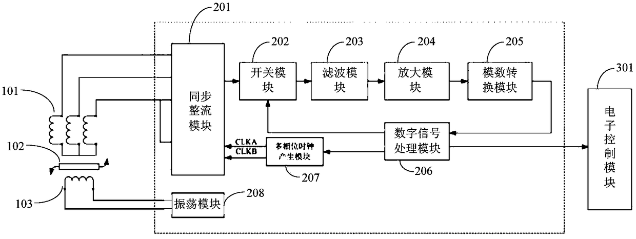
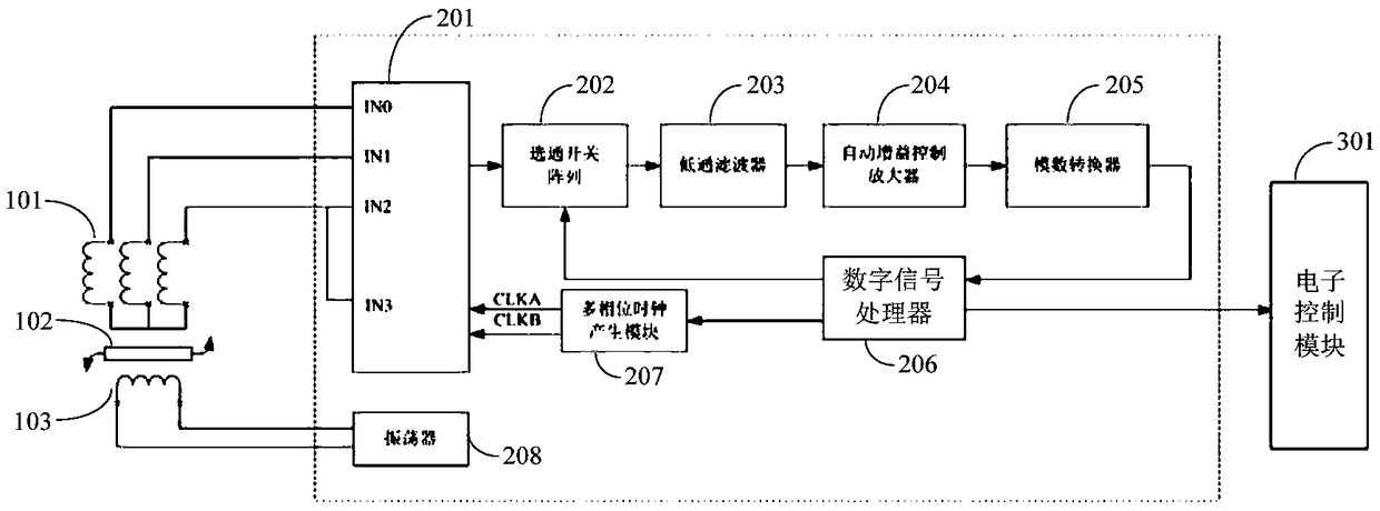
[0020] The above-mentioned signal processing circuit and device for a non-contact position sensor adopts a metal rotor to connect the mechanical device to be measured, and an excitation coil and a plurality of induction coils are set on the PCB as a stator. When the position of the metal rotor changes , due to its specific symmetrical shape, the mutual inductance between the excitation coil and several induction coils on the PCB will change periodically, resulting in a periodically changing induced voltage signal. The induced voltage signal is amplified by an analog signal collector and converted i...


PUM


Abstract

The invention belongs to the technical field of the electronic circuit, and provides a signal processing circuit and device for a non-contact position sensor. An oscillation signal is provided for anexciting coil through an oscillation module, and a plurality of induction coils output corresponding induction signals after the mutual inductance with the exciting coils occurs when a location of therotor is changed, a digital signal is output to a digital signal processing module so as to compute and reduce the location information of the rotor after a synchronization rectification module performs the rectification, a switch module performs the gating, a filter module performs the filtering, an amplification module performs the signal amplification and an analog-digital conversion module performs the analog-to-digital conversion, so that an electronic control module performs analysis processing and makes the corresponding execution control; and meanwhile, a multi-phase clock productionmodule is used for adjusting phases of multiple collection ports in the synchronization rectification module in real time so as to correct the location information; the effect of precisely acquiring and correcting the rotor location information is realized, thereby precisely detecting a mechanical device connected with the rotor.

Description

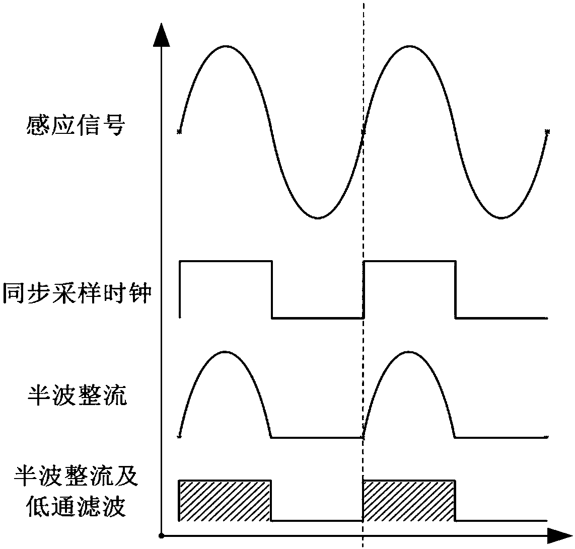
technical field [0001] The invention belongs to the technical field of electronic circuits, and in particular relates to a signal processing circuit and device for a non-contact position sensor. Background technique [0002] With the development of vehicle electronic control systems, non-contact position sensors are widely used in electronic control systems such as automotive electronic power steering systems, accelerator pedals, throttle control, automatic seat adjustment, and rearview mirror adjustment. A typical electromagnetic induction non-contact position sensor has a metal rotor with a specific shape, a PCB single board, and a dedicated signal processing chip. The mutual inductance between the excitation coil and the induction coil on the PCB board will change periodically. Specifically, the sinusoidal signal of the induction coil is filtered by a synchronous rectifier and a low-pass filter and converted into an approximate DC signal, and then the automatic gain contr...

Claims


Application Information

Patent Timeline
Patent Type & Authority Applications(China)
IPC IPC(8): G01B7/00
CPCG01B7/001G01B7/003
Inventor 张欣董火新车诒桓简卫朱奇良
Owner SHENZHEN FLYING FAIRY INTELLIGENT TECH CO LTD
Learn More