


Quick Research
Generate reliable direction feasibility study reports for your R&D in just a few steps.

Technical Q&A
Discover and master advanced knowledge NOW. Basics, ideas, possibilities, all at once.

Find Solutions
As an expert in R&D theories, this can generate solutions to your technical problems instantly.

Evaluate Feasibility
Analyze your overall solution with one click, know your potential R&D risks in advance.

Monitor Landscape
Get weekly tech updates, stay abreast of the latest tech innovations and key insights.
Optical fiber light emitting structure and laser dotting processing method
A technology of light-emitting structure and processing method, which is applied in the direction of semiconductor devices, optics, and light guides of light-emitting elements, to achieve the effects of large coverage area, improved use effect, and improved service life
- Summary
- Abstract
- Description
- Claims
- Application Information
AI Technical Summary
Problems solved by technology
Method used
Image

Examples
Embodiment 1
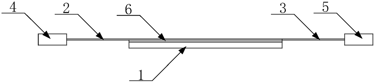
[0039] Such as figure 1 As shown, an optical fiber light-emitting structure includes a reflective sheet 1, an optical fiber layer arranged on the reflective sheet 1, a light source connected to the optical fiber layer, a small hole arranged on the upper side of the optical fiber layer, and an optical fiber layer arranged on the optical fiber layer and the reflective sheet. The bottom layer of transparent glue layer 6 between 1; the optical fiber layer is made up of several optical fibers, the front section of the optical fiber is the light-emitting surface, the rear section is the guiding line, the light-emitting surface of the optical fiber is fixed on the reflective sheet 1, and the leading line ends are connected with the The light source is connected; the small hole or the scribe line is formed after stripping the coating layer of the optical fiber, and the small hole is set against the reflection sheet 1 .
[0040] The small hole is a circular hole, which is mainly obtain...
Embodiment 2
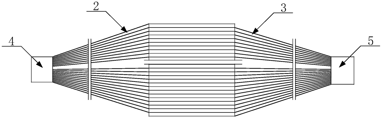
[0049] The difference between this embodiment and embodiment 1 is that, as Figure 4 As shown, the optical fiber also includes an upper optical fiber 9 or a lower optical fiber 10 or a combination of an upper optical fiber 9 and a lower optical fiber 10; the light source also includes an upper light source 11 connected to the upper optical fiber 9 and a lower optical fiber connected to the lower optical fiber 10 Light source 12; the number of the upper light source 11 and the lower light source 12 is at least one.
[0050] While laying the left and right optical fibers horizontally, whether the upper optical fiber and the lower optical fiber are used alone or at the same time will not affect the normal use of the product. It can be selected according to actual needs to improve the scope of application of the product. The upper light source is connected to the upper optical fiber, and the lower light source is connected to the lower optical fiber, so that the part of the optica...
Embodiment 3
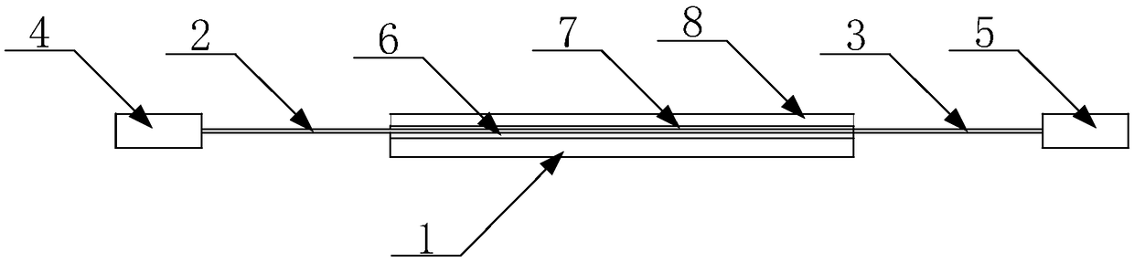
[0056] The only difference between this embodiment and Embodiments 1 and 2 is that figure 2 As shown, the upper side of the optical fiber layer is further provided with a top layer of transparent glue layer 7 and a diffusion sheet 8 in sequence.
[0057] The shape and size of the diffusion sheet need to be consistent with the reflective sheet.
PUM
 Abstract
Description
Claims
Application Information
 - R&D Engineer
- R&D Manager
- IP Professional
- Industry Leading Data Capabilities
- Powerful AI technology
- Patent DNA Extraction
Browse by: Latest US Patents, China's latest patents, Technical Efficacy Thesaurus, Application Domain, Technology Topic, Popular Technical Reports.
© 2024 PatSnap. All rights reserved.Legal|Privacy policy|Modern Slavery Act Transparency Statement|Sitemap|About US| Contact US: help@patsnap.com