Solenoid valve structure with pressure relief mechanism

A solenoid valve and pressure relief technology, applied in valve details, safety valves, balance valves, etc., can solve the problems of high cost, increased processing cost, and complicated structure of the oil passage of the cylinder head, so as to improve work reliability and avoid abnormality. Action, the effect of simplifying the structure of the cylinder deactivation oil passage

Pending Publication Date: 2019-01-18
MIANYANG FULIN PRECISION MACHINING
View PDF0 Cites 4 Cited by
  • Summary
  • Abstract
  • Description
  • Claims
  • Application Information

AI Technical Summary

Problems solved by technology

However, increasing the control oil passage alone will inevitably complicate the structure of the oil passage in the cylinder head, resulting in an increase in processing costs; in addition, after adding the control oil passage, it is necessary to use a double oil passage hydraulic tappet to realize the cylinder stop function, and the double oil passage hydraulic pressure Tappets cost more than single-channel hydraulic tappets

Method used


Image

  • Solenoid valve structure with pressure relief mechanism
  • Solenoid valve structure with pressure relief mechanism
  • Solenoid valve structure with pressure relief mechanism

Examples


Embodiment Construction

[0022] In order to make the object, technical solution and advantages of the present invention clearer, the present invention will be described in detail below in conjunction with the accompanying drawings and specific embodiments. It should be understood that the specific embodiments described here are only used to explain the present invention, not to limit the present invention.

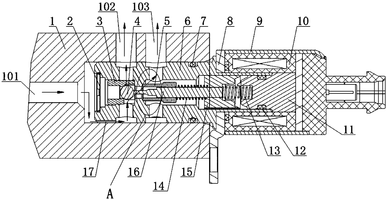
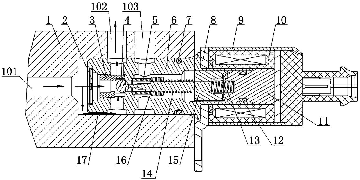
[0023] Such as figure 1 , figure 2 The shown solenoid valve structure with a pressure relief mechanism mainly includes a cylinder head 1, a valve sleeve 6, a bracket 8, a valve housing 9 and a pressure relief mechanism. The cylinder head 1 forms an oil inlet 101, and the cylinder head 1 A bypass oil passage 17 is formed between the valve sleeve and the valve sleeve 6 . The valve casing 9 is provided with a solenoid assembly 10 and a back yoke sleeve 11 , and a bracket 8 is connected between the valve casing 9 and the valve sleeve 6 . A filter screen 2, a plug 3, a return spring 13, a magnetic ...


PUM


Abstract

The invention provides a solenoid valve structure with a pressure relief mechanism. The structure comprises a cylinder cover, a valve sleeve, a magnetic core and the pressure relief mechanism, an oilinlet is formed in the cylinder cover, a by-pass oil passage is formed between the cylinder cover and the valve sleeve, and a control oil passage and a pressure relief oil passage are formed in the socket section between the valve sleeve and the cylinder cover separately; the pressure relief mechanism is arranged between the magnetic core and the valve sleeve, and a movable connecting structure sliding relative to the straight line is formed between the pressure relief mechanism and the valve core; the solenoid valve is powered off, and the engine oil pressure of the control oil passage is higher than set pressure of the pressure relief mechanism, the pressure relief mechanism is pushed open by engine oil, and the oil inlet, the by-pass oil passage, the control oil passage and the pressurerelief oil passage are communicated; when the solenoid valve is energized, the pressure relief passage is closed, and the oil inlet, the by-pass oil passage and the control oil passage are communicated. Accordingly, abnormal action, caused by oil pressure fluctuation, of a cylinder deactivation rocker can be avoided, the cylinder deactivation function requirements can be met by adopting a singleoil passage tappet, and the structure has the prominent advantages of simplifying the oil passage structure, lowering the cost, improving the work reliability and the like.

Description

technical field [0001] The invention relates to the field of electromagnetic valve structure design, in particular to an electromagnetic valve structure with a pressure relief mechanism for cylinder deactivation function. Background technique [0002] Car cylinder deactivation control The control computer of the fuel-saving device determines when and how to deactivate the cylinders according to the vehicle load conditions (throttle valve position, engine speed, vehicle speed, gear position, water temperature, air conditioner, etc.). When cylinder deactivation is required, the intake and exhaust valves of one or more cylinders are immediately closed through the cylinder deactivation mechanism, and the corresponding fuel injection system is also closed. At this time, when the piston is in the compression stroke, the gas in the cylinder is compressed and consumes work; in the suction stroke and expansion stroke, the compressed gas expands and does work externally. Theoreticall...

Claims


Application Information

Patent Timeline
Patent Type & Authority Applications(China)
IPC IPC(8): F16K31/06F16K17/04
CPCF16K31/0675F16K17/0473
Inventor 王波杨生伟任彦平张金伟周强王艳
Owner MIANYANG FULIN PRECISION MACHINING
Why Eureka
Try Eureka