
A column-slab connection device including multiple shear keys

A technology of connecting device and shear key, applied in bridge structure engineering and construction field, can solve problems such as hidden safety hazards of construction workers and clutter on construction site.

Active Publication Date: 2021-09-14
ANHUI TRANSPORT CONSULTING & DESIGN INST
View PDF11 Cites 0 Cited by
  • Summary
  • Abstract
  • Description
  • Claims
  • Application Information

AI Technical Summary

Problems solved by technology

[0002] In the field of traditional structural engineering, the connection between piles and slab beams is mainly formed by hoisting reinforcement cages and cast-in-situ concrete at the construction site. This traditional connection and construction method requires on-site formwork, on-site mixing and pouring of large-volume concrete, which will Causes chaos on the construction site and poses a great safety hazard to construction workers

Method used


Image

  • A column-slab connection device including multiple shear keys
  • A column-slab connection device including multiple shear keys
  • A column-slab connection device including multiple shear keys

Examples


Embodiment 1

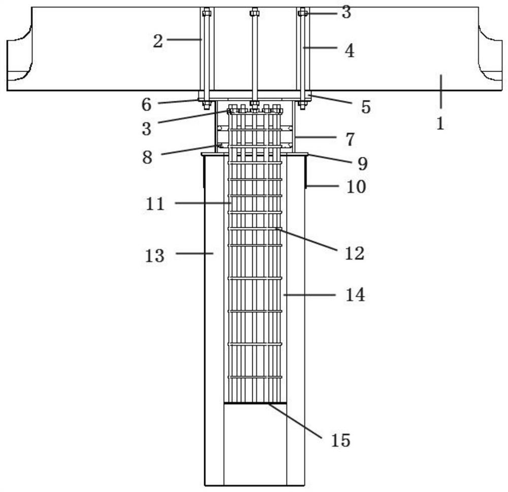
[0023] A column-slab connection device including multiple shear keys, including an upper section assembly, a connection assembly and a lower section assembly.

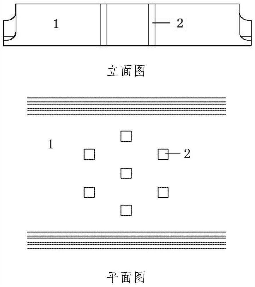
[0024] The upper section assembly includes a prefabricated beam slab 1 . In practice, the prefabricated beam slab 1 includes prefabricated beam slab reserved holes 2 , and the positions of the prefabricated beam slab reserved holes 2 correspond to the positions of the reserved anchor bolt holes on the base steel plate 6 .

[0025] The connection assembly includes a wedge block 5 , a base steel plate 6 , a steel cylinder 7 and a reinforcing hoop 8 on the inner wall of the steel cylinder. During implementation, the wedge block 5 is a cast-in-place or prefabricated structure, which is used for leveling the prefabricated components of the upper section; anchor bolt holes and middle round holes are reserved on the base steel plate 6 for connection with the prefabricated components of the upper section; Tube inner wall rein...

Embodiment 2

[0030] The wedge block 5 can be a prefabricated or cast-in-place component. If the cast-in-place wedge 5 is used, the connection between the upper section component and the connecting component can be implemented by the following methods: hoisting the prefabricated beam slab 1, the prefabricated beam slab 1 is supported by a special bracket, and the center of the beam slab bottom is at a certain distance from the base steel plate 6 . After the positioning and installation of the anchor bolt 4 is completed, the outer formwork of the wedge-shaped block 4 at the bottom of the pouring slab is installed, and then grouting is carried out from the reserved hole 2 of the prefabricated beam slab. The grouting should be full and dense without leaving any voids.

Embodiment 3

[0032] The prefabricated slab 1 can be a prefabricated component or a cast-in-place component. If the cast-in-place beam slab is used, after the positioning and installation of the anchor bolt 4 is completed, on-site grouting with the help of the external formwork is required to realize the connection between the upper section component and the connecting component.


PUM


Abstract

The invention discloses a column-slab connection device including multiple shear keys, which comprises an upper section prefabricated assembly, a connection assembly and a lower section assembly. The prefabricated components of the upper section include prefabricated beams and slabs, the connecting components include wedge blocks, base steel plates, steel cylinders and reinforcement hoops on the inner wall of steel cylinders, and the components of the lower section include reinforcement anchor plates, circular steel plates, steel sleeves, longitudinal steel bars, circular steel bars, and tubular piles The column, core-filling grouting material and pallet steel plate, the prefabricated component of the upper section and the connecting component are connected through anchor bolts, and the connecting component of the lower section is connected with the connecting component through a core-filling steel cage and core-filling grouting material. The invention creates a column-slab connection device including multiple shear keys, which makes the connection between piles and slab beams highly industrialized and prefabricated. Compared with traditional piles and slab-beam connections, the connection device has higher safety and durability stronger. The force is clear and the reliability is strong. While efficiently realizing the rigid connection of the column and the slab, it also greatly realizes the industrialized construction and forms considerable economic benefits.

Description

Technical field: [0001] The invention relates to the field of construction and bridge structure engineering, in particular to a column-slab connection device including multiple shear keys. Background technique: [0002] In the field of traditional structural engineering, the connection between piles and slab girders is mainly formed by hoisting reinforcement cages and cast-in-situ concrete at the construction site. This traditional connection and construction method requires on-site formwork, on-site mixing and pouring of large-volume concrete, which will It causes chaos on the construction site and poses a great potential safety hazard to construction workers. The reliability of the pile-slab joint is entirely determined by the quality of the concrete poured on site, and is largely affected by the site operating environment and weather conditions. With the rise of industrial construction, factory prefabricated assembly of components embodies the concept of green and enviro...

Claims


Application Information

Patent Timeline
Patent Type & Authority Patents(China)
IPC IPC(8): E04B1/48E04B1/38
CPCE04B1/38E04B1/483
Inventor 胡可杨大海曹光伦朱俊于春江吴平平郑建中李剑鸾王胜斌雷进丁楠汪志甜
Owner ANHUI TRANSPORT CONSULTING & DESIGN INST
Learn More