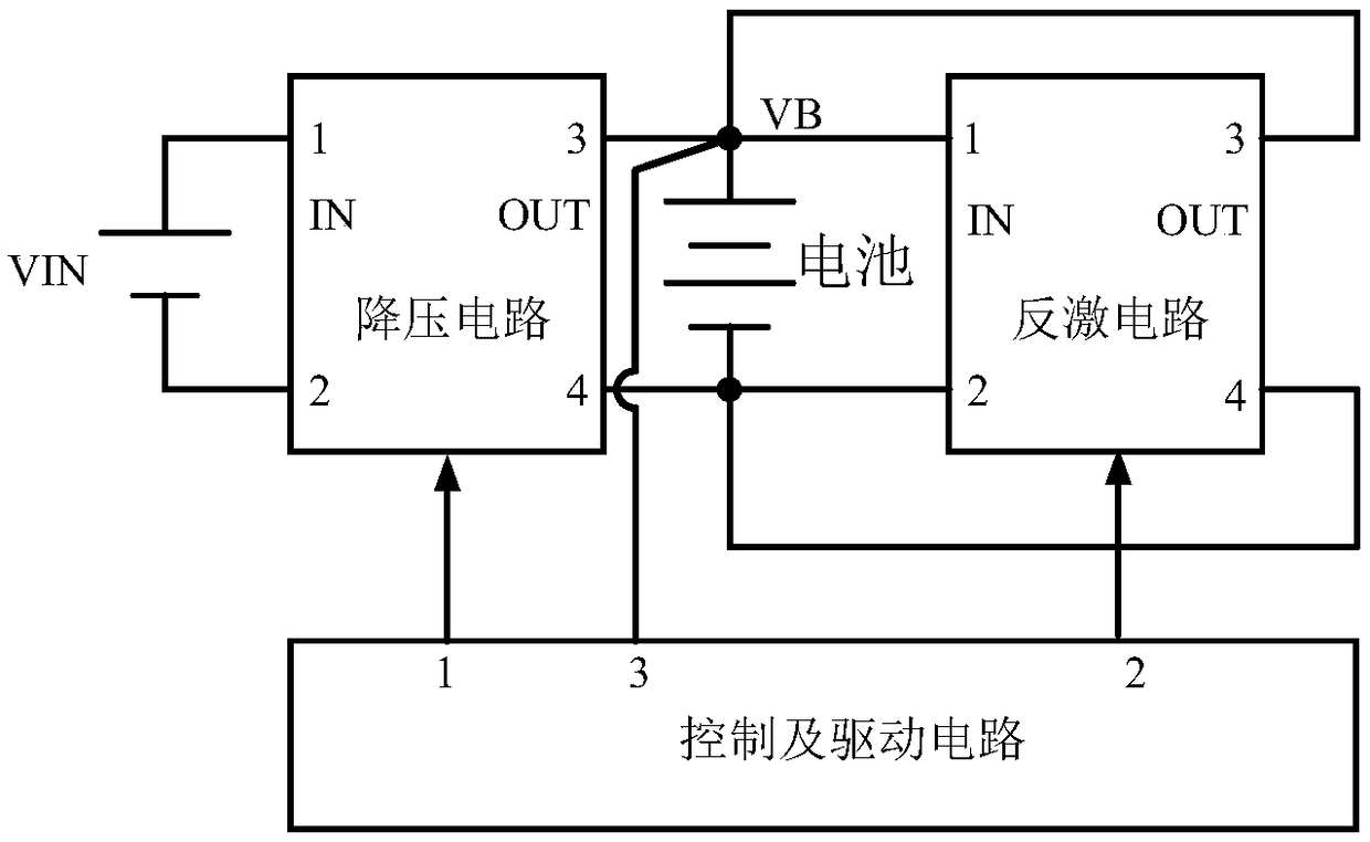
A current control method and a battery fast charging circuit using the method
A current control and battery technology, applied in battery circuit devices, circuit devices, current collectors, etc., can solve the problems of complex control and high system cost, and achieve the effects of simple control, elimination of polarization voltage, and strong structural versatility
- Summary
- Abstract
- Description
- Claims
- Application Information
AI Technical Summary
Problems solved by technology
Method used
Image
Examples
no. 1 example
[0041] image 3 It is the schematic circuit diagram of the first embodiment of the present invention. The step-down circuit includes capacitor C1, power tube Q1, inductor L1, diode D1, and capacitor C2; the flyback circuit includes a power tube protection circuit, a transformer T1, including a primary winding and a secondary winding, power tube Q2, and diode D2. The control and drive circuit includes an input terminal VB, a signal output terminal G1, a signal output terminal G2, and a ground terminal GND;
[0042] In this embodiment, the connection relationship of each circuit for realizing the fast charging of the battery and the function of eliminating the polarization voltage is as follows:
[0043] The drain of the power transistor Q1 is used as the input end of the step-down circuit, and the positive pole is connected to one end of the capacitor C1, and connected to the positive pole of the input power supply VIN; the source of the power transistor Q1 is connected to the...
no. 2 example
[0054] Figure 5 In order to realize the second embodiment of the converter of the present invention to quickly charge the battery and eliminate the polarization voltage function, the difference from the first embodiment is that the step-down circuit adopts a synchronous rectification circuit, and the circuit includes a capacitor C1, a power transistor Q1, and a power transistor Q3 , capacitor C2, inductor L1, the control and drive circuit includes an input terminal VB, a signal output terminal G1, a signal output terminal G2, a signal output terminal G3, and a ground terminal GNG. The connection relationship is as follows:
[0055] The drain of the power transistor Q1 is connected to one end of the input capacitor C1 as the positive pole of the input terminal of the step-down circuit, and is simultaneously connected to the positive pole of the input power supply VIN; the source of the power transistor Q1 is connected to the drain of the power transistor Q3, and is simultaneous...
no. 3 example
[0066] Figure 7 Compared with the first embodiment, the third embodiment of the present invention realizes the fast charging of the battery and the function converter of eliminating the polarization voltage. The connection relationship is as follows:
[0067] The same-named end of the primary winding of the transformer T1 is connected to the first port of the power tube protection circuit, which is used as the positive pole of the input terminal of the flyback circuit, and is connected to the positive pole of the battery at the same time; the opposite-named end of the primary winding of the transformer T1 is connected to the power tube protection circuit The second port of the power tube Q2 drain; the source of the power tube Q2 is connected to the same name end of the secondary winding of the transformer T1, and connected to the negative pole of the battery; the different name end of the secondary winding of the transformer T1 is connected to the anode of the diode D2 The c...
PUM
 Abstract
Description
Claims
Application Information
 - R&D Engineer
- R&D Manager
- IP Professional
- Industry Leading Data Capabilities
- Powerful AI technology
- Patent DNA Extraction
Browse by: Latest US Patents, China's latest patents, Technical Efficacy Thesaurus, Application Domain, Technology Topic, Popular Technical Reports.
© 2024 PatSnap. All rights reserved.Legal|Privacy policy|Modern Slavery Act Transparency Statement|Sitemap|About US| Contact US: help@patsnap.com


