
Integrated redox flow battery stack

A liquid flow battery and liquid flow technology, applied in the field of electric energy storage, can solve the problems of poor electrolyte transmission, bulky volume and weight, and low energy efficiency, so as to reduce the phenomenon of positive and negative electrolyte internal leakage and reduce positive and negative electrolyte leakage. The effect of internal leakage of electrolyte and small volume

Pending Publication Date: 2019-01-15
佛山中量新能科技有限公司
View PDF0 Cites 1 Cited by
  • Summary
  • Abstract
  • Description
  • Claims
  • Application Information

AI Technical Summary

Problems solved by technology

[0006] Existing integrated redox flow batteries are usually composed of conductive plastic plates, electrodes, ion exchange membranes, current collecting plates, diversion tanks, etc., which have many processing components, large length, width and height, bulky volume and weight, and high internal resistance. , Inconvenient assembly, complex structure, difficult processing, poor electrolyte transmission effect, large self-discharge, low power density, low energy efficiency, high cost and other defects, it is difficult to promote and apply on a large scale

Method used


Image

  • Integrated redox flow battery stack
  • Integrated redox flow battery stack
  • Integrated redox flow battery stack

Examples


Embodiment Construction

[0033] The present invention will be further described below in conjunction with accompanying drawing and embodiment, and embodiment does not constitute limitation of the present invention:

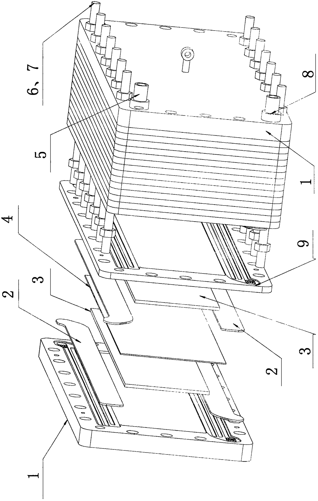
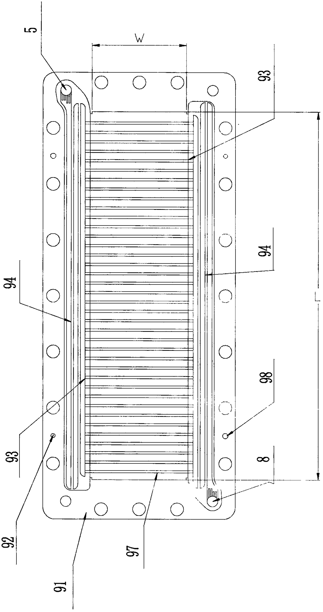
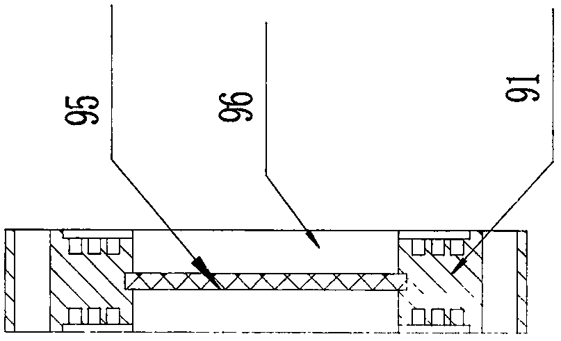
[0034] As shown in the figure, the integrated redox flow battery stack is mainly composed of an integrated liquid flow end frame plate 1, a cover plate 2, an electrode 3, a perfluorinated ion exchange membrane 4, a liquid outlet 5, bolts, nuts 6, 7. It is composed of a liquid inlet 8 and an integrated liquid flow frame plate 9. The integrated liquid flow end frame plate 1 is mainly composed of a liquid flow end frame plate 11, a conductive column 12, a collector plate 13, a conductive plastic plate 95, a liquid outlet 5, a liquid inlet 8, a positioning hole 92, and a positioning pin 98. The integrated liquid flow frame plate 9 is mainly composed of a liquid flow frame plate 91 , a positioning hole 92 , a conductive plastic plate 95 , a liquid outlet 5 and a liquid inlet 8 . The liquid fl...


PUM


Abstract

An integrated redox flow battery stack comprises an integrated liquid flow frame plate (liquid flow frame plate and conductive plastic plate are injection molded at one time), an integrated liquid flow end frame plate (liquid flow end frame plate, conductive plastic plate and current collector plate are molded by one-time injection molding), Fasteners, in which: the integrated liquid flow frame plate is provided with an inlet, Liquid outlet, integrated liquid flow frame plate positive, the access is arrange on that reverse side, outlet bypass flow channel, one end of the liquid inlet branch passage is communicated with the liquid inlet port, the other end of the liquid inlet branch passage is communicated with the long straight U-shaped circuitous groove, the one end of the liquid outlet branch passage is communicated with the liquid outlet, the other end of the liquid outlet branch passage is communicated with the long straight U-shaped circuitous groove, an ion exchange membrane is stuck between adjacent integrated liquid flow frame plates, and the integrated liquid flow frame plate is a liquid flow frame plate and an electrically conductive plastic plate for injection molding; The integrated liquid flow end frame plate is formed by injection molding of the liquid flow end frame plate, the conductive plastic plate and the current collector plate. Electrodes are arranged in the inner frame of the integrated liquid flow frame plate and the inner frame of the integrated liquid flow end frame plate; The integrated liquid flow frame plate, the electrode, the ion exchange membrane and the integrated liquid flow end frame plate are pressed in series by fasteners.

Description

technical field [0001] The invention relates to the field of electric energy storage, and mainly refers to an integrated redox flow battery stack. Background technique [0002] The "Notice on Promoting Electric Energy Storage's Participation in the Pilot Work of the Electric Auxiliary Service Compensation (Market) Mechanism in the "Three North" Region" officially issued by the National Energy Administration is like a ray of spring breeze, opening the door for energy storage to participate in the auxiliary service market for peak regulation and frequency regulation. The entire industry is full of confidence in the future development of energy storage. By 2020, the cumulative installed capacity of energy storage technology in the country will reach 14.5 GW. This data includes heat storage but does not include pumped storage. If we look at the ideal scenario, the above statistics will reach 24.2 GW. The introduction of favorable energy storage development policies and the dual...

Claims


Application Information

Patent Timeline
Patent Type & Authority Applications(China)
IPC IPC(8): H01M8/18H01M8/2483H01M8/0263H01M8/0258
CPCH01M8/0258H01M8/0263H01M8/188H01M8/2483Y02E60/50
Inventor 马东亮谷雨
Owner 佛山中量新能科技有限公司
Learn More