
An anti-electric shock transformer based on a block chain

An anti-electric shock, blockchain technology, applied in the direction of transformer/inductor housing, transformer/inductor cooling, transformer/inductor components, etc. Rainwater enters, avoids leakage of output lines, and has good anti-shock ability.

Inactive Publication Date: 2019-01-15
曾繁洪
View PDF5 Cites 1 Cited by
  • Summary
  • Abstract
  • Description
  • Claims
  • Application Information

AI Technical Summary

Problems solved by technology

[0002] With the sustained, healthy and rapid development of China's economy, the demand for electricity continues to grow rapidly. As the key electrical equipment for power transmission, the market demand for transformers has also maintained a steady growth. When there is AC current in the middle pass, AC magnetic flux is generated in the iron core (or magnetic core), which induces a voltage (or current) in the secondary coil. The anti-shock transformer based on the block chain is designed to concentrate the traditional transformer in a box-type In the housing, it has small size, light weight, low noise, low loss, and high reliability. It is widely used in residential quarters, commercial centers, light stations, airports, factories and mines, enterprises, hospitals, schools and other places, but the existing Blockchain anti-shock transformers have poor anti-shock effect, which can easily lead to electric shock accidents. At the same time, existing blockchain-based transformers are widely used outdoors, many of which are exposed to wind and rain, and the transformer must ensure a certain amount of heat dissipation. Therefore, it cannot be sealed, and it is necessary to prevent external water vapor from entering the inside of the transformer. For this reason, we have designed a blockchain-based anti-shock transformer to solve the problems raised in the above-mentioned background technology

Method used


Image

  • An anti-electric shock transformer based on a block chain
  • An anti-electric shock transformer based on a block chain
  • An anti-electric shock transformer based on a block chain

Examples


Embodiment Construction

[0020] The following will clearly and completely describe the technical solutions in the embodiments of the present invention with reference to the accompanying drawings in the embodiments of the present invention. Obviously, the described embodiments are only some, not all, embodiments of the present invention. Based on the embodiments of the present invention, all other embodiments obtained by persons of ordinary skill in the art without making creative efforts belong to the protection scope of the present invention.

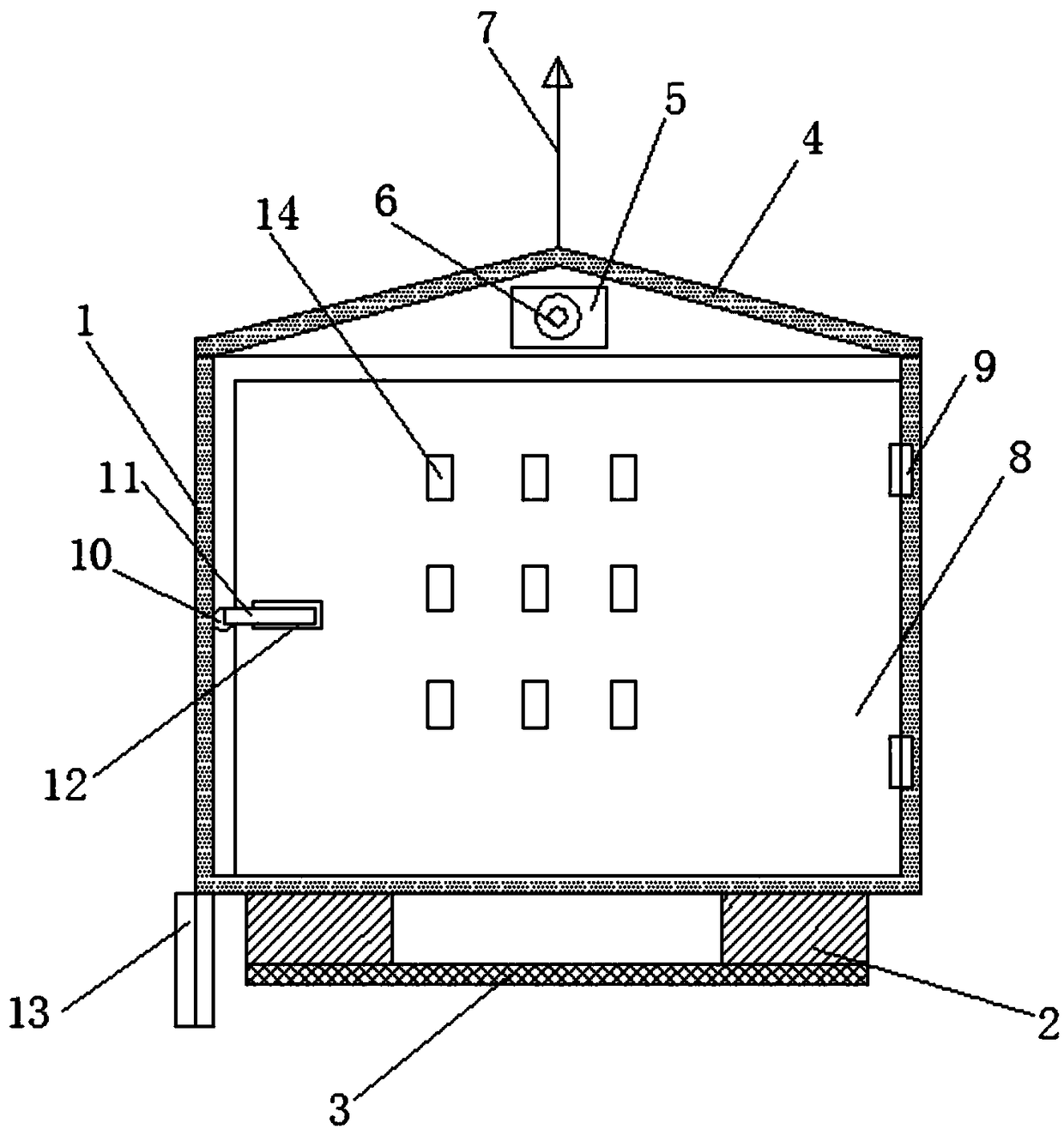
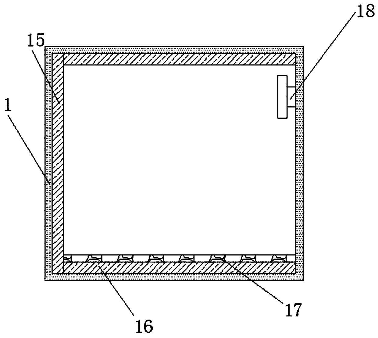
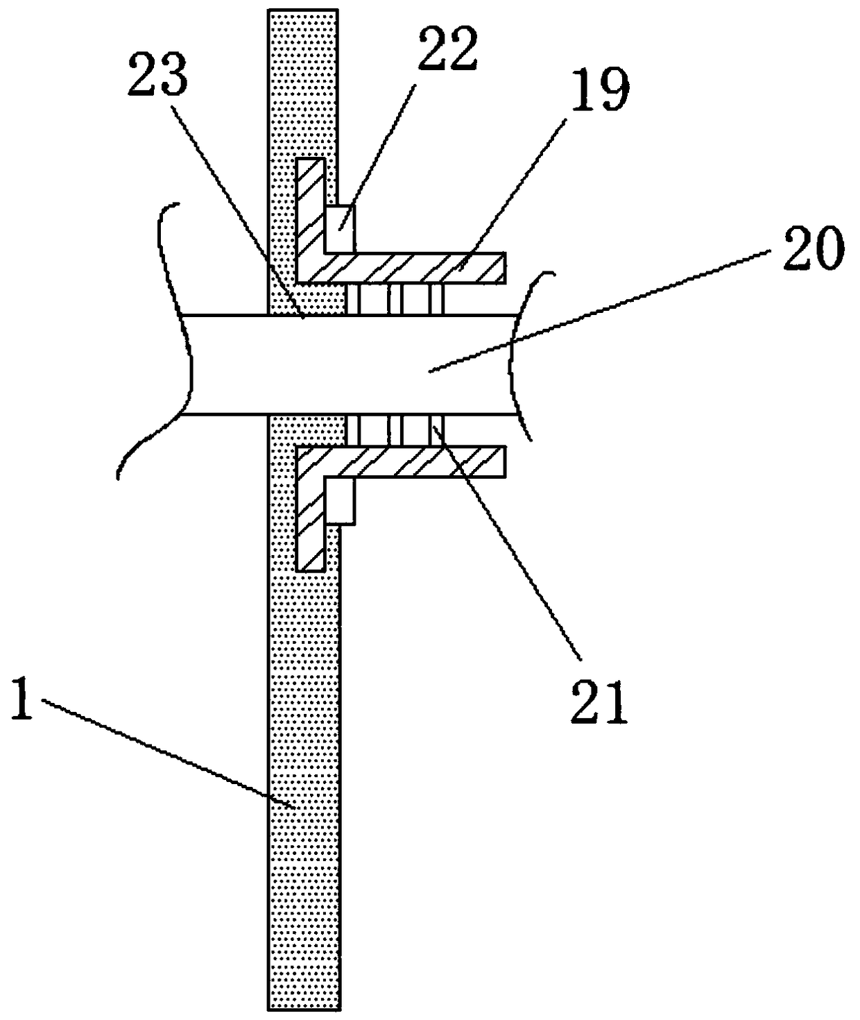
[0021] The present invention provides such Figure 1-3 The shown block chain-based anti-shock transformer includes a housing 1 and a support block 2, the support block 2 is arranged at the lower end of the housing 1, and the lower end of the support block 2 is fixedly connected with an anti-skid plate 3, The upper end of the housing 1 is connected with a swash plate 4, the upper end of the housing 1 is provided with a groove 5, the inside of the groove 5 is eq...


PUM


Abstract

The invention discloses an anti-electric shock transformer based on a block chain, include a housing and a support block, the supporting block is arranged at the lower end of the shell, the lower endof the support block is fixedly connected with an anti-skid plate, the upper end of the shell is connected with an inclined plate, the outer side of the lightning rod is provided with a first insulating sleeve, the front side of the shell is connected with a box door through a hinge, the side surface of the shell is fixedly connected with a vertical baffle plate, the bottom of the shell is fixedlyconnected with a transverse baffle plate, a fixing hook is installed on the side of the shell, the side surface of the shell is provided with a through hole, a second insulating sleeve is fixedly connected to the inside of the through hole, the inside of the second insulating sleeve is provided with a terminal post, An annular convex rib is arranged between the terminal post and the second insulating sleeve, and a sealing ring is connected between the second insulating sleeve and the housing. The invention is convenient to prevent the external rainwater from entering the housing along the boxdoor by setting a vertical baffle plate and a transverse baffle plate, thereby avoiding electric leakage and preventing electric shock accidents.

Description

technical field [0001] The invention belongs to the technical field of power distribution equipment, and in particular relates to a blockchain-based anti-shock transformer. Background technique [0002] With the sustained, healthy and rapid development of China's economy, the demand for electricity continues to grow rapidly. As the key electrical equipment for power transmission, the market demand for transformers has also maintained a steady growth. When there is AC current in the middle pass, AC magnetic flux is generated in the iron core (or magnetic core), which induces a voltage (or current) in the secondary coil. The anti-shock transformer based on the block chain is designed to concentrate the traditional transformer in a box-type In the housing, it has small size, light weight, low noise, low loss, and high reliability. It is widely used in residential quarters, commercial centers, light stations, airports, factories and mines, enterprises, hospitals, schools and oth...

Claims


Application Information

Patent Timeline
IPC IPC(8): H01F27/02H01F27/06H01F27/08H01F27/32H01F27/40
CPCH01F27/02H01F27/025H01F27/06H01F27/085H01F27/324H01F27/402
Inventor 不公告发明人
Owner 曾繁洪
Learn More