A fully automatic bearing testing machine for a mechanical manufacturing system

A mechanical manufacturing, fully automatic technology, applied in the field of automatic bearing testing machines for mechanical manufacturing systems, can solve problems such as affecting the testing efficiency, inflexible testing width, and affecting the normal use of bearings.

Active Publication Date: 2020-06-09
龙岩市双荣机械科技有限公司
View PDF6 Cites 0 Cited by
  • Summary
  • Abstract
  • Description
  • Claims
  • Application Information

AI Technical Summary

Problems solved by technology

[0004] The purpose of the present invention is to provide a fully automatic bearing testing machine for a mechanical manufacturing system to solve the problem that the existing bearing testing machine for a mechanical manufacturing system proposed in the background art has a single detection function for bearings and can only detect The height and width of the bearing are tested, but there are many reasons why the bearing cannot be used. For example, the smoothness of the inner and outer rings will affect the normal use of the bearing, so the machine cannot perform a comprehensive test on the bearing, and the test width is not flexible enough. , the problem that affects the detection efficiency

Method used


Image

  • A fully automatic bearing testing machine for a mechanical manufacturing system
  • A fully automatic bearing testing machine for a mechanical manufacturing system
  • A fully automatic bearing testing machine for a mechanical manufacturing system

Examples


Embodiment Construction

[0029] The technical solutions in the embodiments of the present invention will be clearly and completely described below in conjunction with the accompanying drawings in the embodiments of the present invention. Obviously, the described embodiments are only some of the embodiments of the present invention, not all of them. Based on The embodiments of the present invention and all other embodiments obtained by persons of ordinary skill in the art without making creative efforts belong to the protection scope of the present invention.

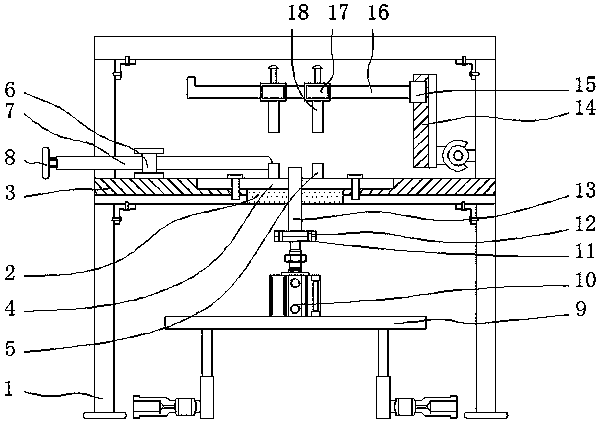
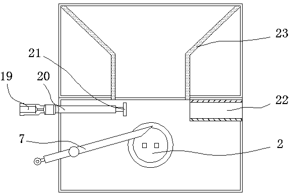
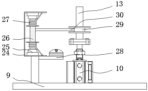
[0030] see Figure 1-5, the present invention provides a technical solution: a fully automatic bearing inspection machine for a mechanical manufacturing system, including a support frame 1, a through hole 2, a sliding groove 3, a sliding plate 4, a first clamping block 5, a rotating shaft 6, and a vibrating rod 7. Vibration sensor 8, lifting table 9, servo motor 10, connecting plate 11, bolt 12, inner ring connecting pipe 13, sliding frame 14, c...


PUM


Abstract

The invention relates to a fully automatic bearing testing machine for a mechanical manufacturing system, which includes a support frame and an inner ring connecting pipe. A through hole is arranged in the middle part of the inner wall at the upper end of the support frame, and sliding grooves are arranged at the upper ends of both sides of the through hole. The inside of the sliding groove is inlaid with a sliding plate, and the upper end of the sliding plate is connected with a first clamping block on the side close to the centerline of the support frame, and the left side of the upper end of the support frame is fixed with a rotating shaft, and the front of the rotating shaft is provided with Vibrating rod; the beneficial effect of the present invention is: through the sliding plate, it can drive the first clamping block to slide on the support frame, and can be adjusted according to the specifications of the tested bearing, and the protruding part of the sliding plate can move the outer ring of the bearing If the bottom is supported, the inner ring can be exposed from the through hole, which is convenient for the vibration sensor to be inserted into the inner ring of the bearing, and the bearing can be clamped by the first clamp block, so that the bearing can be fixed and the bearing of the vibration sensor The degree of lubricity is tested.

Description

technical field [0001] The invention relates to the technical field of bearing detection for mechanical manufacturing systems, in particular to a fully automatic bearing testing machine for mechanical manufacturing systems. Background technique [0002] When the bearing is in use, it needs to be installed in the equipment to match the size and length of the bearing hole. In the bearing production process, the proportional dimension of the bearing often appears out of tolerance, mainly manifested in the height and diameter of the ferrule and the bearing assembly due to the out-of-tolerance of the groove position. If the tolerance is too high, it will cause the situation that it cannot be installed and used normally during actual installation and use, so it needs to be tested after the bearing is produced. [0003] The bearing detection machine used in the existing mechanical manufacturing system has too single detection function for bearings, and it can only detect the height...

Claims


Application Information

Patent Timeline
Patent Type & Authority Patents(China)
IPC IPC(8): G01M13/045
CPCB07C5/06G01B5/02G01B5/28G01M13/04G01M13/045
Inventor 洪颖龙建宇白云
Owner 龙岩市双荣机械科技有限公司
Why Eureka
Try Eureka