
Inner side wall structure of vertical low-temperature container and vertical low-temperature container

A low-temperature container and wall structure technology is applied to the outer wall of container structure, container discharge method, pressure container and other directions to achieve the effects of increasing conduction path, reducing thickness and reducing heat leakage

Pending Publication Date: 2019-01-15
GUANGDONG POWER GRID CO LTD +1
View PDF0 Cites 0 Cited by
  • Summary
  • Abstract
  • Description
  • Claims
  • Application Information

AI Technical Summary

Problems solved by technology

[0005] The invention provides an inner wall structure of a vertical cryogenic container and a vertical cryogenic container, and solves the technical problem of how to reduce heat leakage along the side wall of the neck tube

Method used


Image

  • Inner side wall structure of vertical low-temperature container and vertical low-temperature container
  • Inner side wall structure of vertical low-temperature container and vertical low-temperature container

Examples


Embodiment Construction

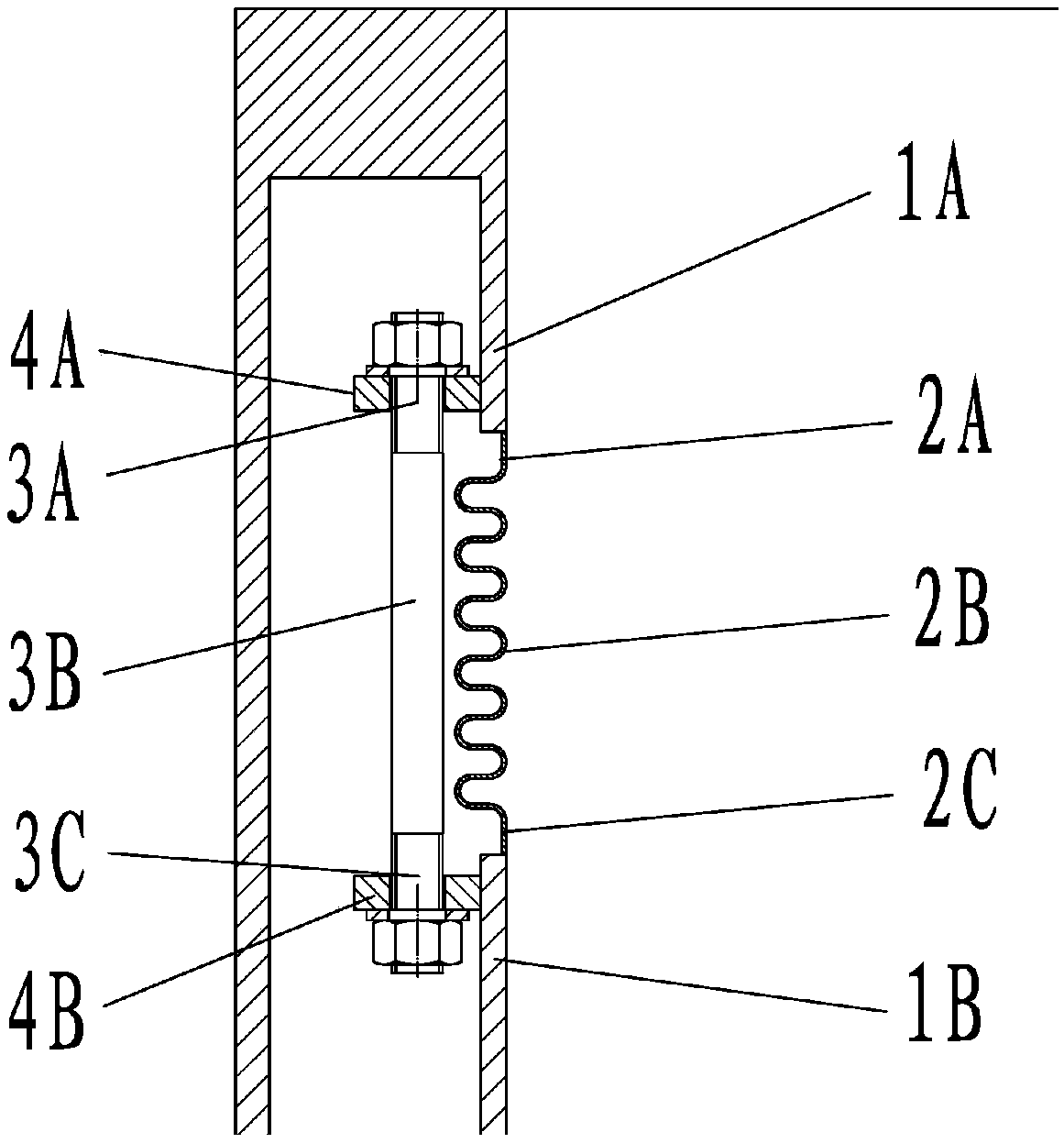
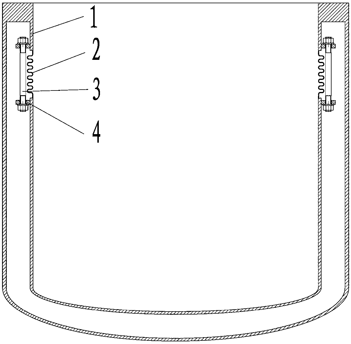
[0032] Embodiments of the present invention provide an inner wall structure of a vertical cryogenic container and the vertical cryogenic container, which solve the technical problem of how to reduce heat leakage along the side wall of the neck tube.

[0033] In order to make the purpose, features and advantages of the present invention more obvious and understandable, the technical solutions in the embodiments of the present invention will be clearly and completely described below in conjunction with the accompanying drawings in the embodiments of the present invention. Obviously, the following The described embodiments are only some, not all, embodiments of the present invention. Based on the embodiments of the present invention, all other embodiments obtained by persons of ordinary skill in the art without making creative efforts belong to the protection scope of the present invention.

[0034] see figure 1 , the present invention provides an embodiment of the inner wall st...


PUM


Abstract

The invention provides an inner side wall structure of a vertical low-temperature container and the vertical low-temperature container, wherein the inner side wall structure of the vertical low-temperature container comprises a metal corrugated pipe expansion joint, wherein a first end of the metal corrugated pipe expansion joint is fixedly connected with a room temperature end of the inner side wall of the vertical low-temperature container; a second end of the metal corrugated pipe expansion joint is fixedly connected with the low-temperature end of the inner side wall of the vertical low-temperature container. The side wall thickness of a neck pipe of the vertical low-temperature container is reduced through the metal corrugated pipe expansion joint; meanwhile, the conduction path is increased, so that the heat leakage along the neck pipe side wall is reduced.

Description

technical field [0001] The invention relates to the technical field of cryogenic containers, in particular to an inner wall structure of a vertical cryogenic container and the vertical cryogenic container. Background technique [0002] Cryogenic container is a device used to hold low-temperature media (such as liquid nitrogen, liquid oxygen, liquid helium, etc.). The French scientist Dewar first proposed a container with a double-wall structure in 1892, which achieved better heat preservation. Effect. The current cryogenic containers basically adopt this double-wall structure, so the cryogenic containers are also commonly referred to as "Dewars". Heat leakage is one of the most important technical indicators in the design of cryogenic containers. Its purpose is to minimize the volatilization of the cryogenic medium in the cryogenic container due to heat absorption. [0003] The heat leakage of the cryogenic vessel is mainly composed of three parts: the simplified body (mul...

Claims


Application Information

Patent Timeline
Patent Type & Authority Applications(China)
IPC IPC(8): F17C1/12F17C13/00
CPCF17C1/12F17C13/002F17C2203/0629F17C2223/013F17C2260/031
Inventor 宋萌段新辉盛超赵永发赵兵李力罗运松夏亚君程文锋史正军林友新
Owner GUANGDONG POWER GRID CO LTD
Learn More