Engine piston blank and machining method thereof

An engine and piston technology, used in engine components, machines/engines, pistons, etc., can solve problems such as higher requirements for high-temperature fatigue performance, high risk of cracking failure, and throat fatigue cracks, so as to improve fatigue strength and reduce throat. The risk of cracking failure, the effect of refining the metallographic structure

Inactive Publication Date: 2019-01-15
湖南江滨机器(集团)有限责任公司
View PDF5 Cites 1 Cited by
  • Summary
  • Abstract
  • Description
  • Claims
  • Application Information

AI Technical Summary

Problems solved by technology

But its disadvantage is that the thickness of the piston head is mostly solidified compared with other thinner areas such as the skirt, and the solidification time is long, and the grain grows sufficiently, resulting in a coarse material structure in this area, especially at the throat of the combustion chamber. The material structure of the part is coarse. With the continuous increase of the explosion pressure, the high temperature fatigue performance of the material at the throat of the combustion chamber of the piston head is higher, resulting in fatigue cracks at the throat and cracking of the head.
[0003] At present, the piston blank generally adopts the traditional core-pulling metal gravity casting with the top riser and the side gate. The riser is directly set on the top surface of the blank head. Larger margin, longer time-consuming
Since the throat of the combustion chamber machined is located in the thick part below the riser, the material structure is coarse, the fatigue strength is low, and the risk of potential cracking and failure is relatively high

Method used


Image

  • Engine piston blank and machining method thereof
  • Engine piston blank and machining method thereof

Examples


Embodiment Construction

[0024] The core of the present invention is to provide an engine piston blank. By setting the annular groove, failures such as throat fatigue cracks and head cracks can be effectively avoided, materials can be saved, and the quality of the finished piston product can be improved. Another core of the present invention is to provide a processing method for the above-mentioned engine piston blank.

[0025] In order to enable those skilled in the art to better understand the solution of the present invention, the present invention will be further described in detail below in conjunction with the accompanying drawings and specific embodiments.

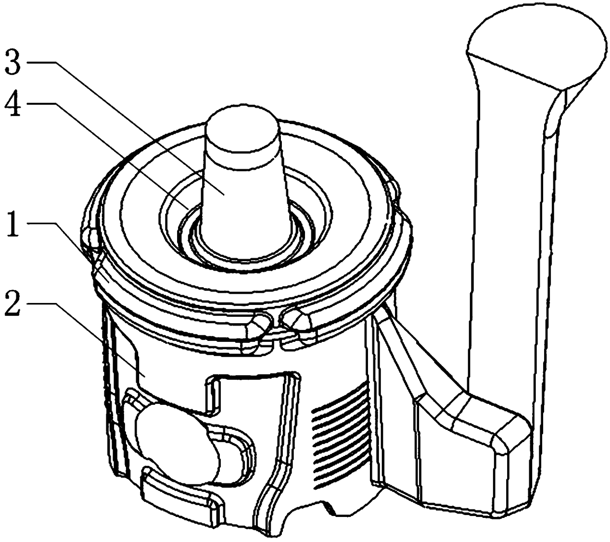
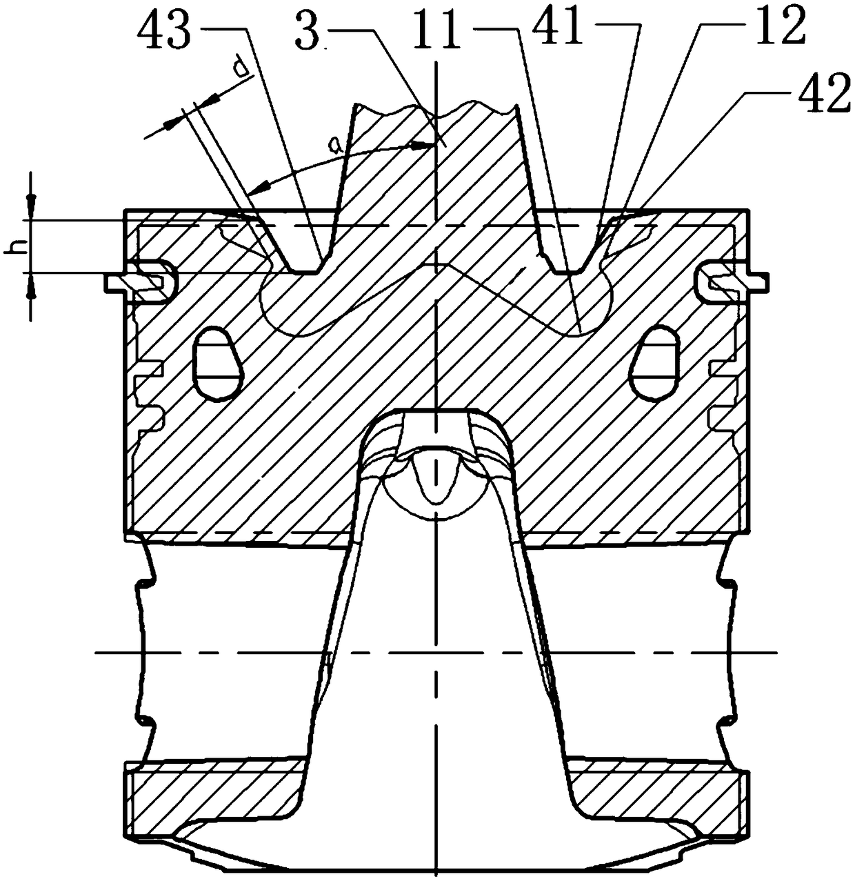
[0026] Please refer to figure 1 and figure 2 , figure 1 It is a structural schematic diagram of a specific embodiment of the engine piston blank provided by the present invention; figure 2 It is a schematic cross-sectional view of a specific embodiment of the engine piston blank provided by the present invention.

[0027] The specific...


PUM


Abstract

The invention discloses an engine piston blank which comprises a skirt portion and a head portion. A dead head is arranged on the top surface of the head portion. The top surface of the head portion is provided with an annular groove which surrounds the dead head and is recessed downwards. The bottom surface of the annular groove is close to the bottom surface of the combustion chamber of a pistonfinished product. The inner side wall of the annular groove is the outer peripheral side face of the dead head. The outer side wall of the annular groove serves as a machining positioning surface andis positioned close to the throat of the piston finished product. Machining allowance layers are arranged between the machining positioning surface and the throat, and also between the bottom surfaceof the annular groove and the bottom surface of the combustion chamber. The general shape of the combustion chamber and the throat is directly cast, and the metallographic structure of a local area is refined. The method is easy to realize and the effect is better. Meanwhile, the cost is lower, and the fatigue strength is improved. The purpose of greatly reducing the cracking failure risk of thethroat is achieved. A formed blank surface is used as a machining positioning surface for subsequent machining, and then the follow-up mechanical machining is carried out. The piston quality is improved. The invention further discloses a machining method of the engine piston blank.

Description

technical field [0001] The invention relates to the field of engine manufacturing, in particular to an engine piston blank. In addition, the invention also relates to a processing method for an engine piston blank. Background technique [0002] At present, the engine piston generally adopts the gravity casting process of the bottom core-pulling metal mold. Its advantage is that it complies with the characteristics of the piston skirt, which is thin and thick, and can better realize the sequential solidification from bottom to top during the casting process of the piston blank. It is beneficial to prevent shrinkage porosity and pore defects in the piston head, and better guarantee the casting quality of the product. But its disadvantage is that the thickness of the piston head is mostly solidified compared with other thinner areas such as the skirt, and the solidification time is long, and the grain grows sufficiently, resulting in a coarse material structure in this area, e...

Claims


Application Information

Patent Timeline
Patent Type & Authority Applications(China)
IPC IPC(8): F02F3/00F02F3/26B23P15/10
CPCB23P15/10F02F3/00F02F3/26
Inventor 王熹朱茂春朱亿鹏黄德威廖从来贺礼财郑鹏
Owner 湖南江滨机器(集团)有限责任公司
Why Eureka
Try Eureka