
Lapping component of circular tube beam and girder

A technology of round tubes and components, which is applied in the field of overlapping components between round tube beams and girders, and can solve problems such as insufficient structural strength, insufficient torsional rigidity, and insufficient rigidity

Pending Publication Date: 2019-10-18
SAIC-GM-WULING AUTOMOBILE CO LTD
View PDF0 Cites 0 Cited by
  • Summary
  • Abstract
  • Description
  • Claims
  • Application Information

AI Technical Summary

Problems solved by technology

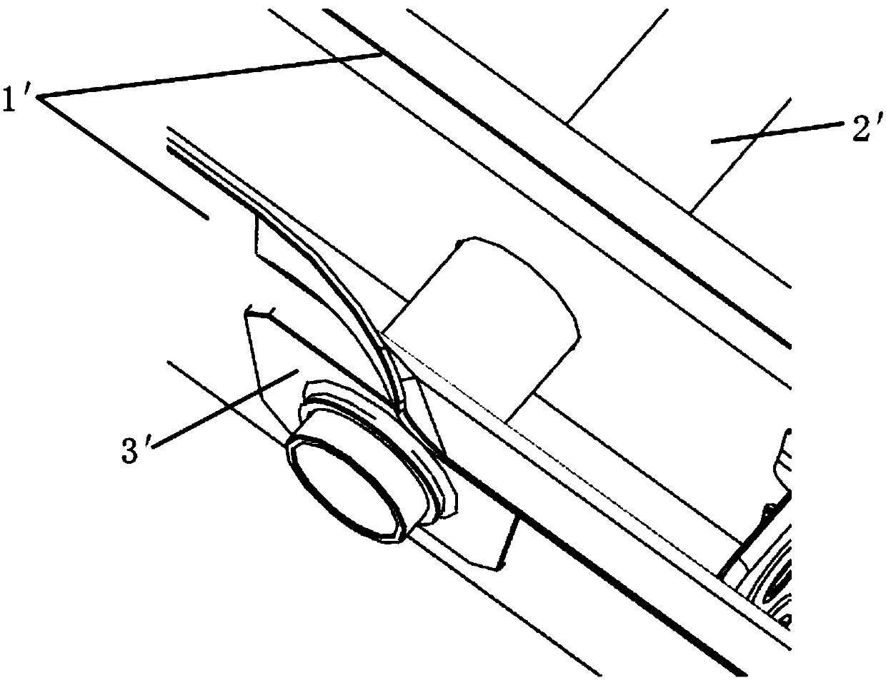
[0003] 1. Insufficient strength at the joints of girder 1′, round tube beam 2′ and round tube beam reinforcement plate 3′: girder 1′, round tube beam 2′ and girder external reinforcement plate 3′ are connected by solder joints and secondary welding , when the structure bears the load transmitted by the chassis suspension, fuel tank and muffler, the structural strength is insufficient, and there is a risk of failure;
[0004] 2. Insufficient bending and torsional rigidity: The girder 1′ and the round tube girder 2′ are connected by secondary welding, and there is no reinforcing plate inside the girder as a support, so there is a problem of insufficient rigidity

Method used


Image

  • Lapping component of circular tube beam and girder
  • Lapping component of circular tube beam and girder
  • Lapping component of circular tube beam and girder

Examples


Embodiment Construction

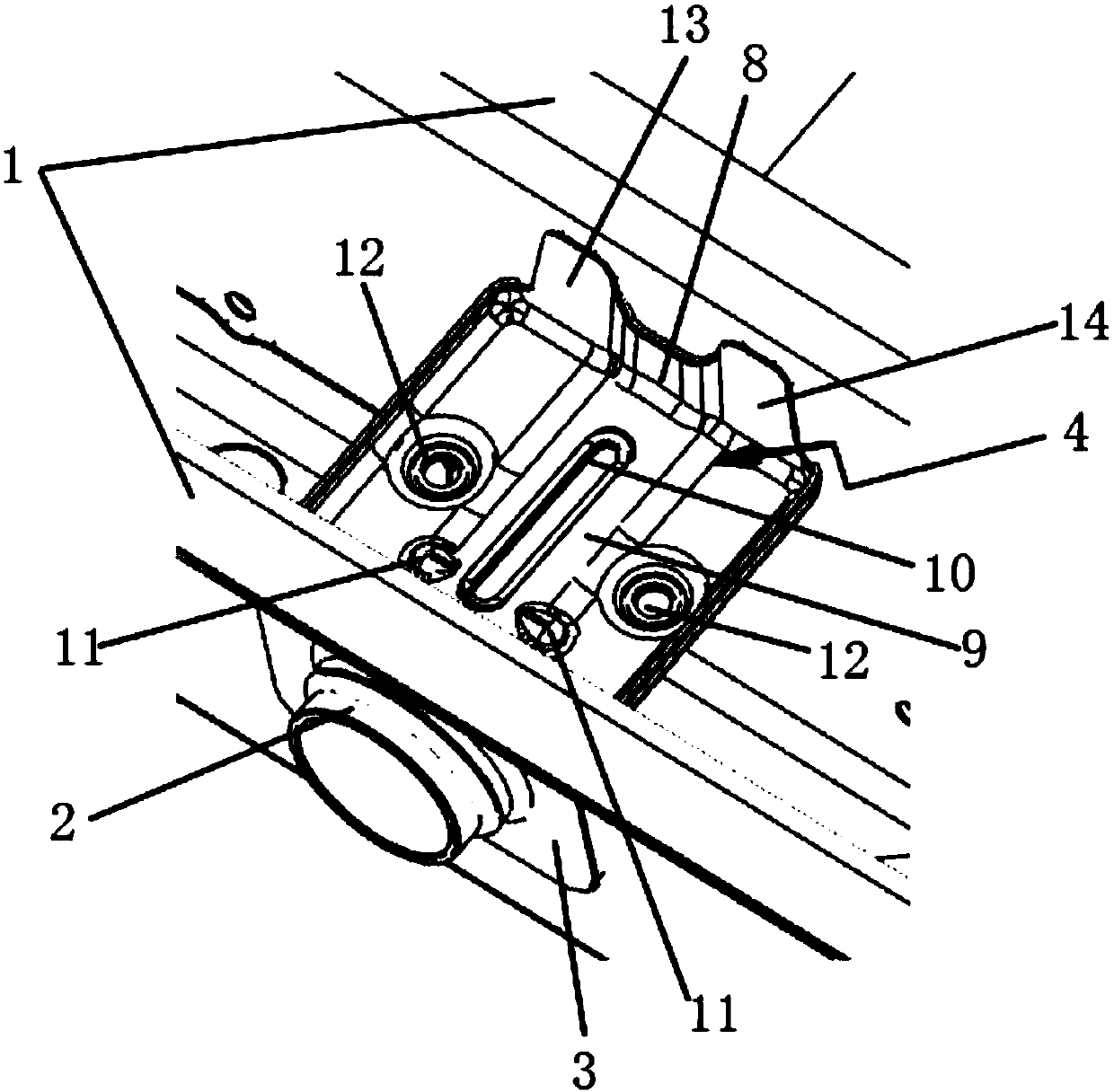
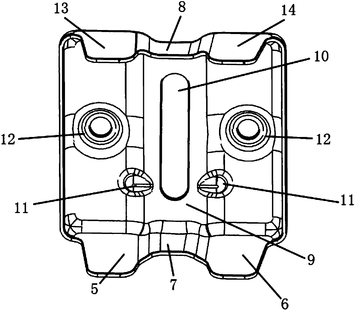
[0026] The following with attached figure 2 and image 3 A lap joint assembly of a circular tube beam and a girder of the present invention is further described in detail. Instructions attached figure 2 The oblique front direction is front, the oblique back direction is rear, the left side direction is left, the right side direction is right, the upper side direction is up and the lower side direction is down.

[0027] For a lap joint assembly between a circular tube beam and a girder of the present invention, please refer to figure 2 and image 3 As shown, it includes a round tube beam 2, a girder 1, a girder outer reinforcement plate 3 and a girder inner sealing plate 4, the front end of the round tube girder 2 passes through the inside of the girder 1, and the front end of the round tube girder 2 passes through the The outer reinforcing plate 3 of the girder is fixed on the outside of the girder 1 , the inner sealing plate 4 of the girder is fixed inside the girder 1...


PUM


Abstract

The invention discloses a lapping component of a circular tube beam and a girder. The lapping component of the circular tube beam and the girder comprises the circular tube beam, the girder, a girderexternal reinforcing plate and a girder internal sealing plate; the front end of the circular tube beam penetrates through the interior of the girder; the front end of the circular tube beam penetrates through the girder external reinforcing plate and is fixed on the external side of the girder; the girder internal sealing plate is fixed in the girder; and the bottom of the girder internal sealingplate is fixedly connected with the upper side of the circular tube beam. According to the lapping component of the circular tube beam and the girder, the structural load transmission path is effectively optimized, the cracking risk of the lapping part of the circular tube beam and the girder is effectively reduced, the connection point stress is reduced while the durability of a part is improved, the safety performance is high, the torsional rigidity of a whole vehicle is improved, and the NVH performance of the whole vehicle is improved.

Description

technical field [0001] The invention relates to a lap joint assembly of a round tube beam and a girder, in particular to a lap joint assembly of a round tube beam and a girder in a commercial vehicle body. Background technique [0002] At present, the lap joint structure between the round tube beam and the girder of the traditional commercial vehicle is relatively simple, such as figure 1 As shown, it includes a girder 1', a round tube beam 2' and a girder outer reinforcing plate 3', the round tube beam 2' passes through the inner plate of the girder 1', and the front end of the round tube beam is provided with a girder outer reinforcing plate 3' For reinforcement, but this structure has the following problems: [0003] 1. Insufficient strength at the joints of girder 1′, round tube beam 2′ and round tube beam reinforcement plate 3′: girder 1′, round tube beam 2′ and girder external reinforcement plate 3′ are connected by solder joints and secondary welding , when the stru...

Claims


Application Information

Patent Timeline
IPC IPC(8): B62D21/00
CPCB62D21/00
Inventor 李朋飞韦利宁陆毅初刘昌乐王永虎
Owner SAIC-GM-WULING AUTOMOBILE CO LTD
Learn More