
Circulating cooling water system and automatic drainage device thereof

A technology of circulating cooling water and automatic drainage, applied in the direction of oxidized water/sewage treatment, water/sludge/sewage treatment, natural water treatment, etc., which can solve the problem of the short distance between the water surface and the exhaust valve port and the degassing effect of the degassing tower decline, high levels of ozone gas, etc.

Pending Publication Date: 2019-01-15
SHANGHAI LIGHT IND RES INST
View PDF0 Cites 0 Cited by
  • Summary
  • Abstract
  • Description
  • Claims
  • Application Information

AI Technical Summary

Problems solved by technology

[0003] There are two main problems with the automatic exhaust valve: firstly, because the chamber of the conventional exhaust valve on the market is small, resulting in a small gas capacity, and the particularity of the ozone treatment circulating cooling water technology causes the ozone gas content in the degassing tower to decrease. Higher, which will make the distance between the water surface and the exhaust valve very close, and it is easy to bring out the water when the exhaust valve is opened to exhaust
[0004] Due to the above-mentioned defects of the automatic exhaust valve, the degassing effect of the degassing tower will decrease. If this problem is not solved, the failure rate of the whole set of equipment will be greatly increased, which will lead to the problem of ozone leakage, which will damage human health and harm the human body. Negative effects on the surrounding environment

Method used


Image

  • Circulating cooling water system and automatic drainage device thereof
  • Circulating cooling water system and automatic drainage device thereof
  • Circulating cooling water system and automatic drainage device thereof

Examples


Embodiment Construction

[0022] In order to make the above objects, features and advantages of the present invention more comprehensible, specific implementations of the present invention will be described in detail below in conjunction with the accompanying drawings.

[0023] In the following description, many specific details are set forth in order to fully understand the present invention, but the present invention can also be implemented in other ways than those described here, so the present invention is not limited by the specific embodiments disclosed below.

[0024] As indicated in this application and claims, the terms "a", "an", "an" and / or "the" do not refer to the singular and may include the plural unless the context clearly indicates an exception. Generally speaking, the terms "comprising" and "comprising" only suggest the inclusion of clearly identified steps and elements, and these steps and elements do not constitute an exclusive list, and the method or device may also contain other st...


PUM


Abstract

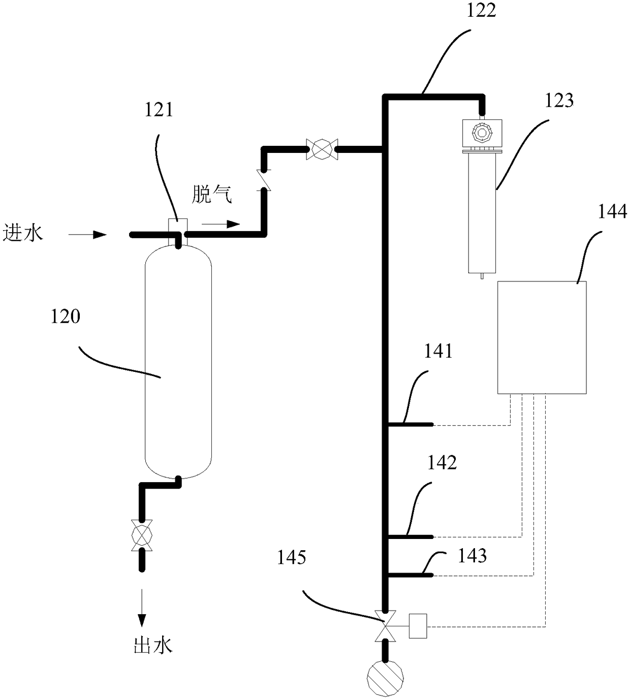
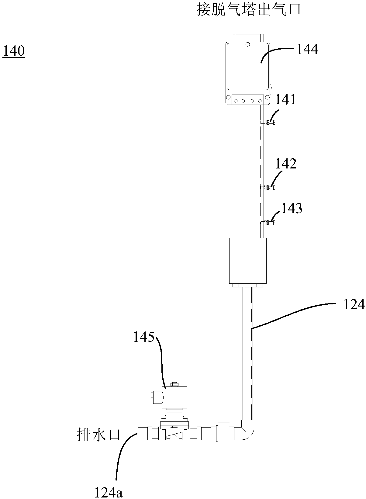
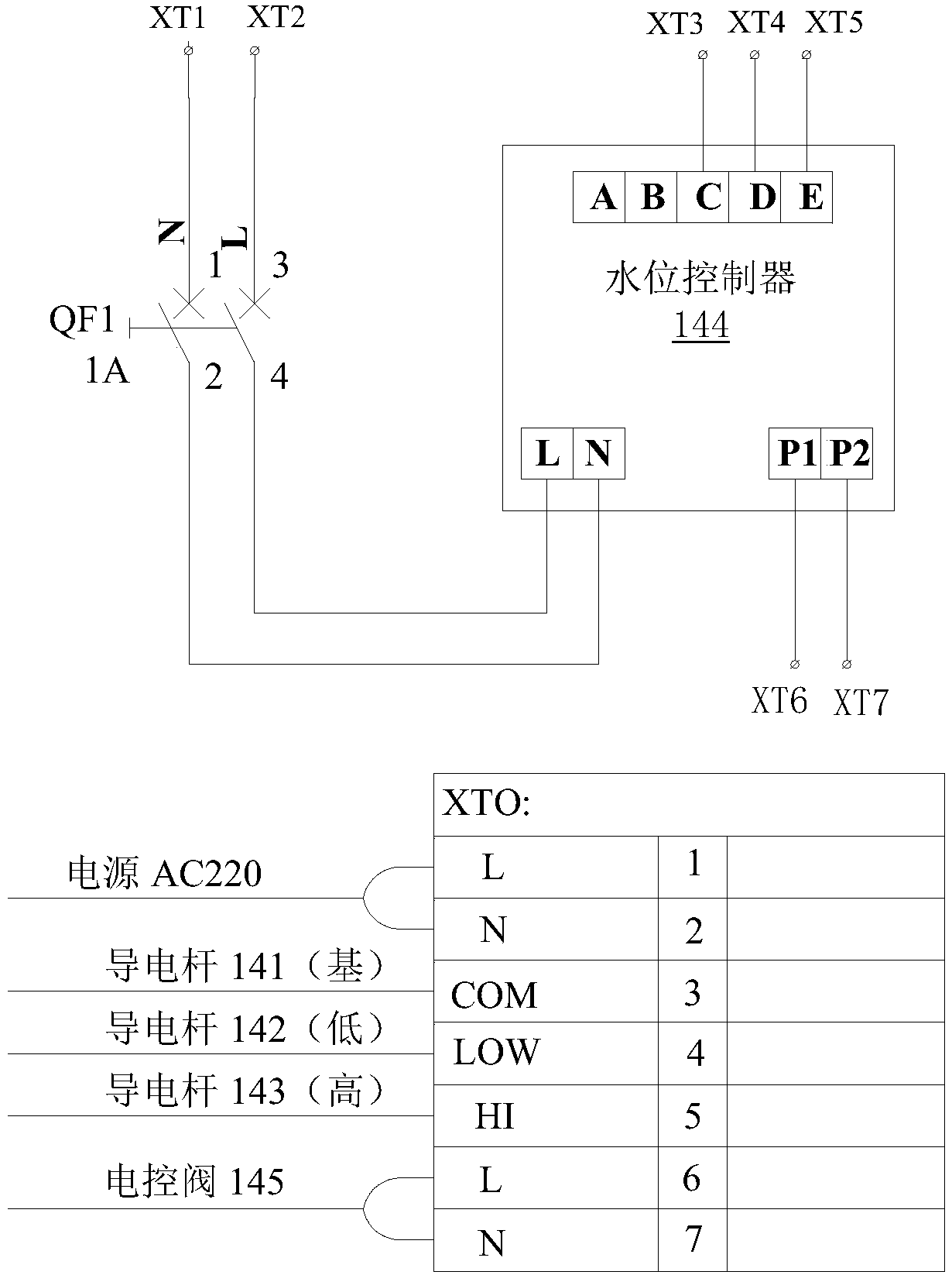
The invention provides a circulating cooling water system and an automatic drainage device thereof. The automatic drainage device includes a plurality of conductive rods, a water level controller andan electric control valve. The plurality of conductive rods are arranged at a trap pipeline of a degassing tower in the circulating cooling water system, the trap pipeline is connected to the air outlet of the degassing tower, and the plurality of conductive rods are arranged at different heights. The water level controller has a plurality of input ends and at least one output end, the plurality of input ends are respectively connected to the plurality of conductive rods, the resistance value of the conductive rods is detected for detecting the water level of the trap pipeline, and a drainagecontrol signal is output according to the water level. The electric control valve is arranged at the drainage port of the trap pipeline and is connected to the at least one output end, and is opened and closed according to the drainage control signal.

Description

technical field [0001] The invention mainly relates to the field of circulating cooling water treatment, in particular to an automatic drainage device for a circulating cooling water system. Background technique [0002] Currently, there is an Advanced Oxidation Process (Advanced Oxidation Processes, AOP) technology using ozone gas as a treatment source to treat circulating cooling water. Due to the physical characteristics of the unstable molecular structure of ozone gas, in the process of processing circulating cooling water, there will always be a part of the gas that is not completely dissolved in the water, but exists in the system in the form of gas. Due to the smell of ozone and its strong oxidizing properties, if a large amount of ozone accumulates, it will have a negative impact on the surrounding environment. This requires adding a degassing tower to the system to decompose and discharge the part of the ozone that is not dissolved in water. An automatic exhaust va...

Claims


Application Information

Patent Timeline
IPC IPC(8): C02F1/78C02F103/02
CPCC02F1/78C02F2103/023
Inventor 冷佳俊李德良
Owner SHANGHAI LIGHT IND RES INST
Learn More