A self-locking folding unmanned aerial vehicle with stably rotating wings

A folding and unmanned aerial vehicle technology, applied in the field of unmanned aerial vehicles, can solve the problems of automatic locking, unreliable wing rotation, low stability and safety, etc., to reduce tilt or shake, reduce friction, The effect of improving stability

Pending Publication Date: 2019-01-15
成都云鼎智控科技有限公司
View PDF7 Cites 2 Cited by
  • Summary
  • Abstract
  • Description
  • Claims
  • Application Information

AI Technical Summary

Problems solved by technology

[0006] The present invention overcomes the deficiencies of the prior art, provides a foldable UAV whose wings can rotate stably and can be automatically positioned and locked, and solves the problem of unreliability, stability and safety when the wings of the existing UAV rotate. The problem of low stability and unable to lock automatically

Method used


Image

  • A self-locking folding unmanned aerial vehicle with stably rotating wings
  • A self-locking folding unmanned aerial vehicle with stably rotating wings
  • A self-locking folding unmanned aerial vehicle with stably rotating wings

Examples


Embodiment 1

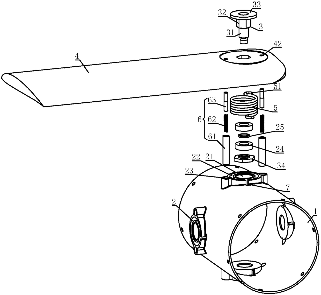
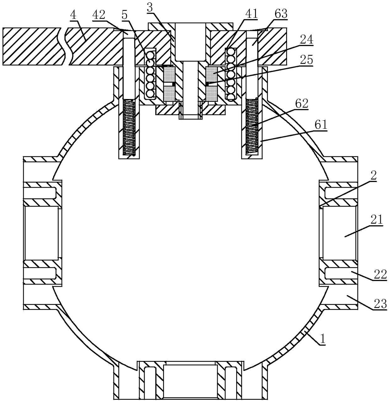
[0037]A foldable unmanned aerial vehicle with stable rotation and self-locking wings, including a bulkhead 1, a plurality of mounting seats 2 are arranged on the bulkhead 1, a mounting hole 21 is provided in the middle of the mounting seat 2, and a machine tool is sleeved in the mounting hole 21. Wing rotating shaft 3, one end of wing rotating shaft 3 is connected with wing 4; Mounting seat 2 is also provided with bulkhead annular groove 22, and bulkhead annular groove 22 is concentric with mounting hole 21, and wing 4 is provided with wing annular groove 41, A torsion spring 5 is sleeved in the bulkhead annular groove 22, and the other end of the torsion spring 5 is sleeved in the wing annular groove 41. One end of the torsion spring 5 is engaged with the bulkhead 1, and the other end of the torsion spring 5 is engaged with the wing. 4 snapping; the mounting seat 2 is provided with a positioning installation hole 23, and a locking mechanism 6 is installed in the positioning in...

Embodiment 2

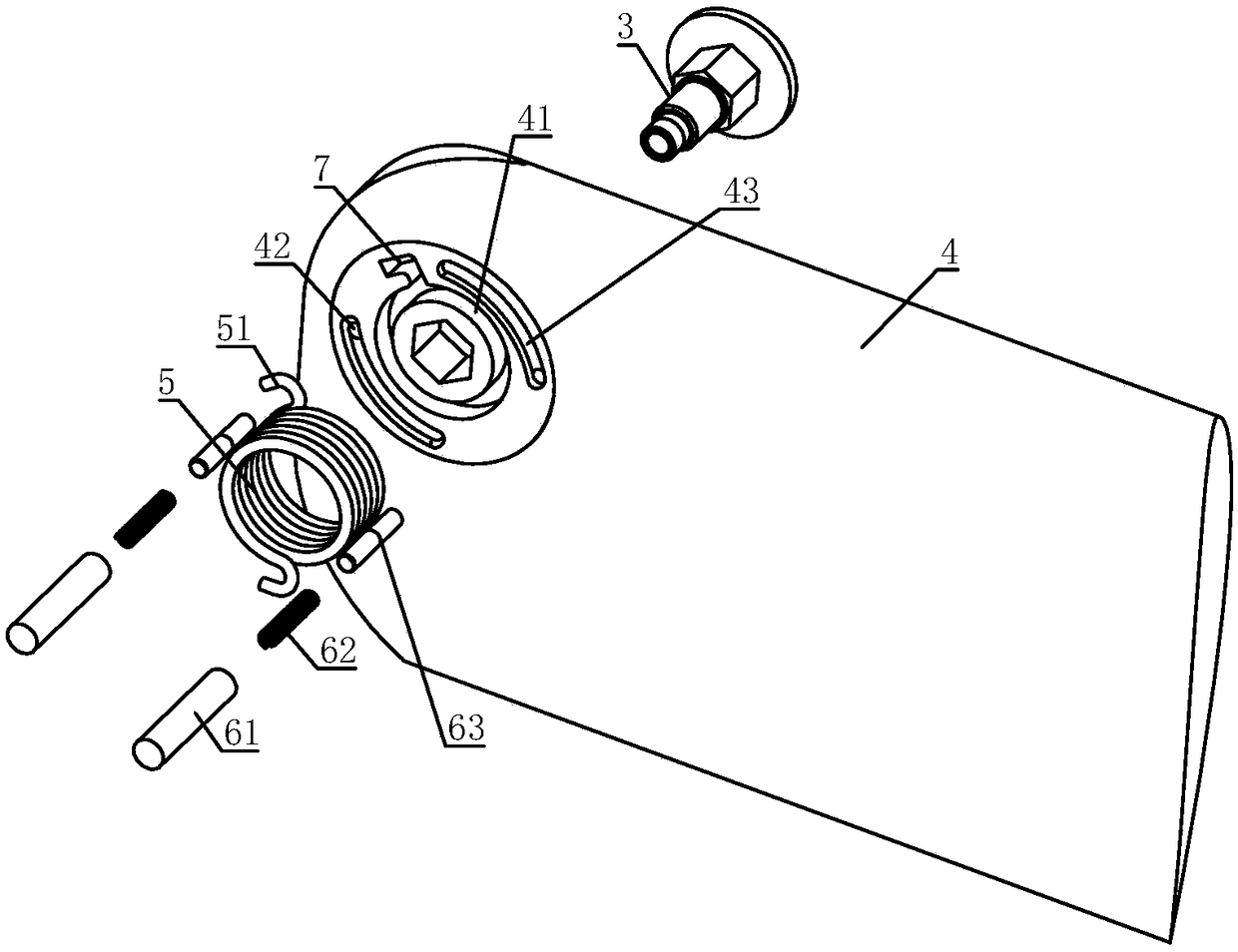
[0042] On the basis of Embodiment 1, L-shaped grooves 7 are arranged on the bulkhead 1 and the wing 4, and the L-shaped groove 7 on the bulkhead 1 communicates with the annular groove 22 of the bulkhead, and the L-shaped groove 7 on the wing 4 The groove 7 communicates with the annular groove 41 of the wing; both ends of the torsion spring 5 are bent into a hook 51, and the hook 51 near the end of the bulkhead 1 snaps into the L-shaped groove 7 on the bulkhead 1, close to the wing The hook 51 at one end of the 4 is snapped into the L-shaped groove 7 on the wing 4.

[0043] The hooks 51 at both ends of the torsion spring 5 are snapped into the L-shaped groove 7, so that one end of the torsion spring 5 is fixed relative to the bulkhead 1, and the other end of the torsion spring 5 is fixed relative to the wing 4, and the torsion spring 5 is in the process of torsion. The wing 4 can rotate relative to the bulkhead 1, so that the wing 4 is unfolded or retracted. The hook 51 is lim...

Embodiment 3

[0045] On the basis of Embodiment 1 or Embodiment 2, two bearings 24 are installed between the wing shaft 3 and the mounting hole 21, and a spacer 25 is set on the wing shaft 3, and the spacer 25 is located between the two bearings. Between 24.

[0046] The bearing 24 can effectively reduce the friction force when the wing 4 rotates, further improves the stability of the wing 4 during rotation, and reduces the situation that the wing 4 is tilted or shaken. The spacer 25 can separate the two bearings 24 to prevent the rollers of the two bearings 24 from rubbing against each other.


PUM


Abstract

The invention relates to the field of unmanned aerial vehicles (UAVs), in particular to a self-locking folding UAV with stably rotating wings. The UAV comprises a bulkhead, wherein a plurality of mounting seats are arranged on the bulkhead, a mounting hole is arranged in the middle of the mounting seats, an airfoil rotating shaft is sleeved in the mounting hole, and one end of the airfoil rotatingshaft is connected with the airfoil. The mounting seats are also provided with a bulkhead annular groove, the bulkhead annular groove is concentric with the mounting hole, the wing is provided with awing annular groove, a torsion spring is sleeved in the bulkhead annular groove, the other end of the torsion spring is sleeved in the wing annular groove, one end of the torsion spring is engaged with the bulkhead, and the other end of the torsion spring is engaged with the wing. A locating mounting hole is arranged on that mounting base, a locking mechanism is arranged in the positioning mounting hole, a locking hole is arranged on the wing, and the locking mechanism is engaged with the wing when the wing is deployed. The invention provides a folding type unmanned aerial vehicle whose wingcan stably rotate and can achieve automatic positioning and locking.

Description

technical field [0001] The invention relates to the field of unmanned aerial vehicles, in particular to a foldable unmanned aerial vehicle whose wings rotate stably and are self-locking. Background technique [0002] In the barrel-launched UAV, due to the very narrow lateral space, when the UAV is in the barrel, the wings need to be folded. When the UAV is launched and flies out of the barrel, the wings need to be automatically deployed and locked in position to provide lift for the UAV, thereby ensuring the normal flight of the UAV. Folding wings have the advantages of small lateral size, convenient box storage and transportation, and are especially suitable for barrel-launched UAVs. [0003] For the barrel-type launch UAV, the folding and unfolding locking mechanism of the wing needs to meet the conditions of reliable connection, simple mechanism, rapid deployment, firm locking, light weight, small size, and good aerodynamic shape. At present, the common wing folding met...

Claims


Application Information

Patent Timeline
Patent Type & Authority Applications(China)
IPC IPC(8): B64C39/02B64C1/30B64C3/56
CPCB64C1/30B64C3/56B64C39/02
Inventor 唐冰陈绪安刘以建
Owner 成都云鼎智控科技有限公司
Why Eureka
Try Eureka