Air blowing system with rotary air pipe

A technology of rotating air and air ducts, which is applied in the field of air blowing systems, can solve problems such as time-consuming and laborious, fixed blowing nozzles, and low operating efficiency, and achieve high efficiency and high quality of completion

Inactive Publication Date: 2019-01-15
CHONGQING KEBEN TECH
View PDF0 Cites 0 Cited by
  • Summary
  • Abstract
  • Description
  • Claims
  • Application Information

AI Technical Summary

Problems solved by technology

[0002] In the process of metal processing, it is necessary to blow the surface of the metal workpiece, and the air blowing system is used to make the air flow on the metal surface. Most of the existing air blowing systems are fixed nozzles or manual blowing. The fixed type is fast, but its blowing The nozzle is fixed so that the nozzle can blow to its corresponding workpiece position, and other positions cannot be blown quickly, resulting in uneven blowing and affecting the blowing effect; while manual blowing can be flexible for multiple workpieces to ensure quality, but the operation Inefficient, time-consuming and labor-intensive, which increases the labor cost of the enterprise, and is not convenient for large-scale and high-efficiency implementation

Method used


Image

  • Air blowing system with rotary air pipe
  • Air blowing system with rotary air pipe

Examples


Embodiment 1

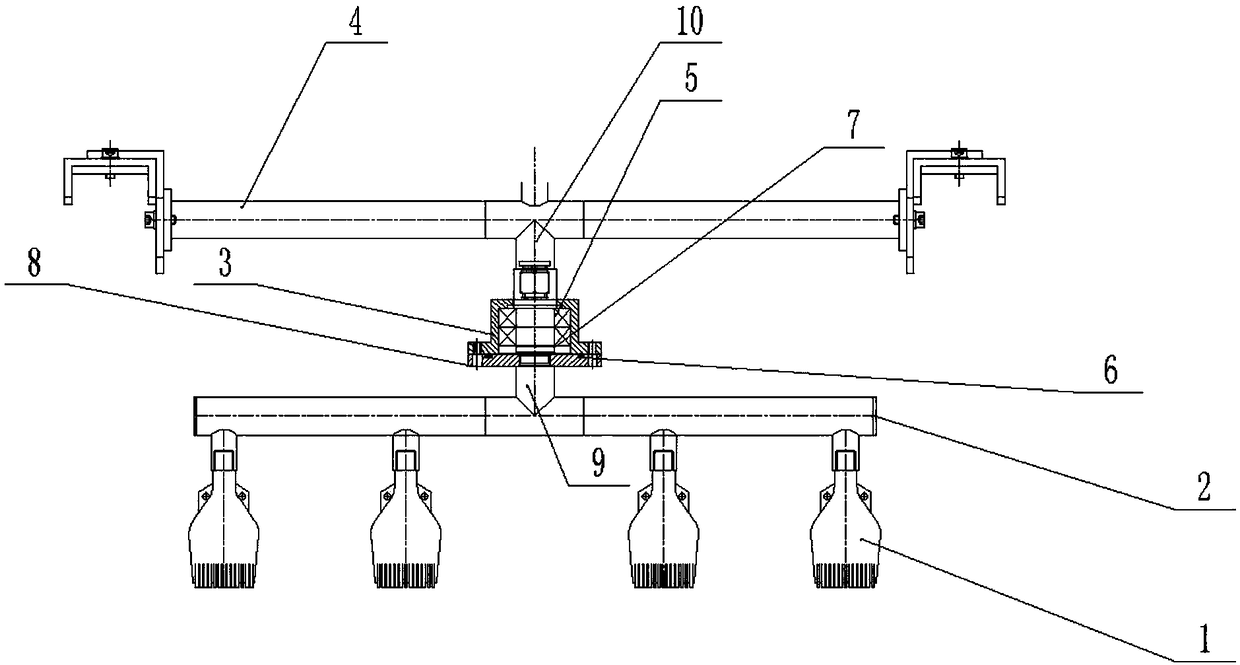
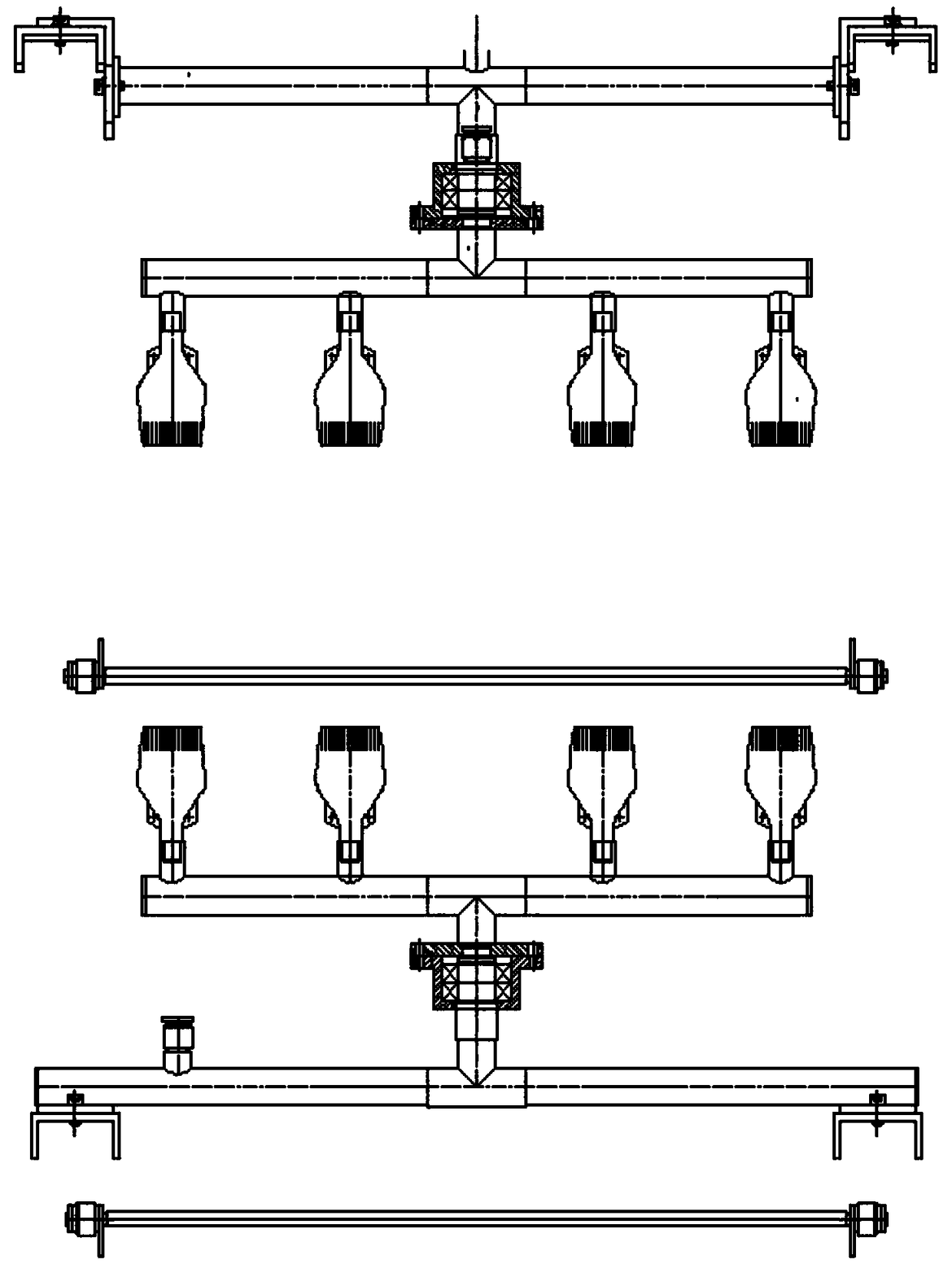
[0016] Please refer to the figure, in the embodiment of the present invention, a blowing system with a rotating air duct includes a blowing nozzle 1, an air duct 2 and a fixed air duct 4; a plurality of blowing nozzles 1 are fixed on the air duct 2, and Evenly distributed on the air pipe 2, the rotating main pipe 9 is connected to the midpoint of the air pipe 2 through a tee, and the branch pipe 10 is connected to the fixed air pipe 4, and the branch pipe 10 is connected to the rotating body 3 through the rotating body. On the main pipe 9, and the rotating body 3 communicates with the rotating main pipe 9 and the branch pipe 10, so that the wind in the fixed air pipe 4 enters the rotating body 3 through the branch pipe 10, and then enters the rotating main pipe 9 from the rotating body 3 And enter in the air pipe 2, blow out by the mouthpiece 1 on it.

[0017] The rotating body 3 is fixedly connected to the connecting flange 8 welded to the end of the rotating main pipe 9 by b...

Embodiment 2

[0020] The fixed air duct 4 is connected with a plurality of branch pipes 10, and the branch pipes 10 are all connected with the same structure as the branch pipes 10 in Embodiment 1, so that multiple groups of air blowing systems can operate simultaneously.

Embodiment 3

[0022] The system can be arranged opposite to each other so that the blowing nozzles 1 on both sides are relatively blown, and air can be blown from both sides correspondingly.


PUM


Abstract

The invention relates to the field of metal machining, and particularly discloses an air blowing system with a rotary air pipe. The air blowing system comprises a plurality of blowing nozzles, the airpipe and a fixed air pipe. The blowing nozzles are fixed to the air pipe and uniformly distributed on the air pipe, a rotating main pipeline is connected to the middle point of the air pipe through atee joint, a branch pipe communicates with the fixed air pipe, the branch pipe is rotatably connected to the rotating main pipeline through a rotating body, and the rotating body communicates with the inner portions of the rotating main pipeline and the branch pipe, so that air in the fixed air pipe enters the rotating body through the branch pipe, enters the rotating main pipeline from the rotating body, then enters the air pipe, and is blown out through the blowing nozzles on the air pipe. The rotation of the blowing nozzles is realized by the action of air flow rather than additionally driving. The blowing nozzles realize the effect of air changing from point to surface by simple design. The air blowing system not only has high efficiency, but also has high completion quality.

Description

technical field [0001] The invention relates to the field of metal processing, in particular to an air blowing system with a rotating air duct. Background technique [0002] In the process of metal processing, it is necessary to blow the surface of the metal workpiece, and the air blowing system is used to make the air flow on the metal surface. Most of the existing air blowing systems are fixed nozzles or manual blowing. The fixed type is fast, but its blowing The nozzle is fixed so that the nozzle can blow to its corresponding workpiece position, and other positions cannot be blown quickly, resulting in uneven blowing and affecting the blowing effect; while manual blowing can be flexible for multiple workpieces to ensure quality, but the operation It is inefficient, time-consuming and labor-intensive, increases the labor cost of the enterprise, and is not convenient for large-scale and efficient implementation. Therefore, it is necessary to improve the existing blowing sy...

Claims


Application Information

Patent Timeline
Patent Type & Authority Applications(China)
IPC IPC(8): B05B1/00
CPCB05B1/005
Inventor 朱兴德
Owner CHONGQING KEBEN TECH
Why Eureka
Try Eureka