
Motor, axial fan using said motor, and axial fan used for indoor machine of air conditioner

An axial flow and fan technology, applied in the direction of electromechanical devices, control mechanical energy, electrical components, etc., can solve the problems of increased length of motor 1, decreased capacity of indoor units, and complicated configuration, so as to reduce the length of the axial direction and reduce the The effect of the number of parts and simple structure

Inactive Publication Date: 2006-01-11
NIDEC SHIBAURA CORP
View PDF0 Cites 0 Cited by
  • Summary
  • Abstract
  • Description
  • Claims
  • Application Information

AI Technical Summary

Problems solved by technology

[0005] In such a motor 1, the sleeve 7 is required as a component to realize the rotor 5, and there is a problem of increasing the number of components and complicating the configuration.
[0006] In addition, this motor 1 is provided with the bearings 10 and 11 arranged at intervals in the axial direction from the stator 4 and the rotor 5 at both ends in the axial direction of the casing 9 surrounding the stator 4 and the rotor 5 from the outside as described above. Therefore, There is a problem that the axial length of the motor 1 is increased and the structure is enlarged
[0007] In addition, when the motor 1 is connected to, for example, an axial flow fan, etc., it is necessary to connect to the connection portion protruding from the above-mentioned bearing 11 of the rotary shaft 8. Therefore, there is a problem that the structure including the axial flow fan becomes larger.
[0008] In addition, as the above-mentioned axial flow fan, in the case of an indoor unit of an air conditioner, the axial length of the motor 1 is increased so that the axial length of the axial flow fan is limited, and the generated air volume is reduced to reduce the performance of the indoor unit.

Method used


Image

  • Motor, axial fan using said motor, and axial fan used for indoor machine of air conditioner
  • Motor, axial fan using said motor, and axial fan used for indoor machine of air conditioner
  • Motor, axial fan using said motor, and axial fan used for indoor machine of air conditioner

Examples


no. 1 Embodiment

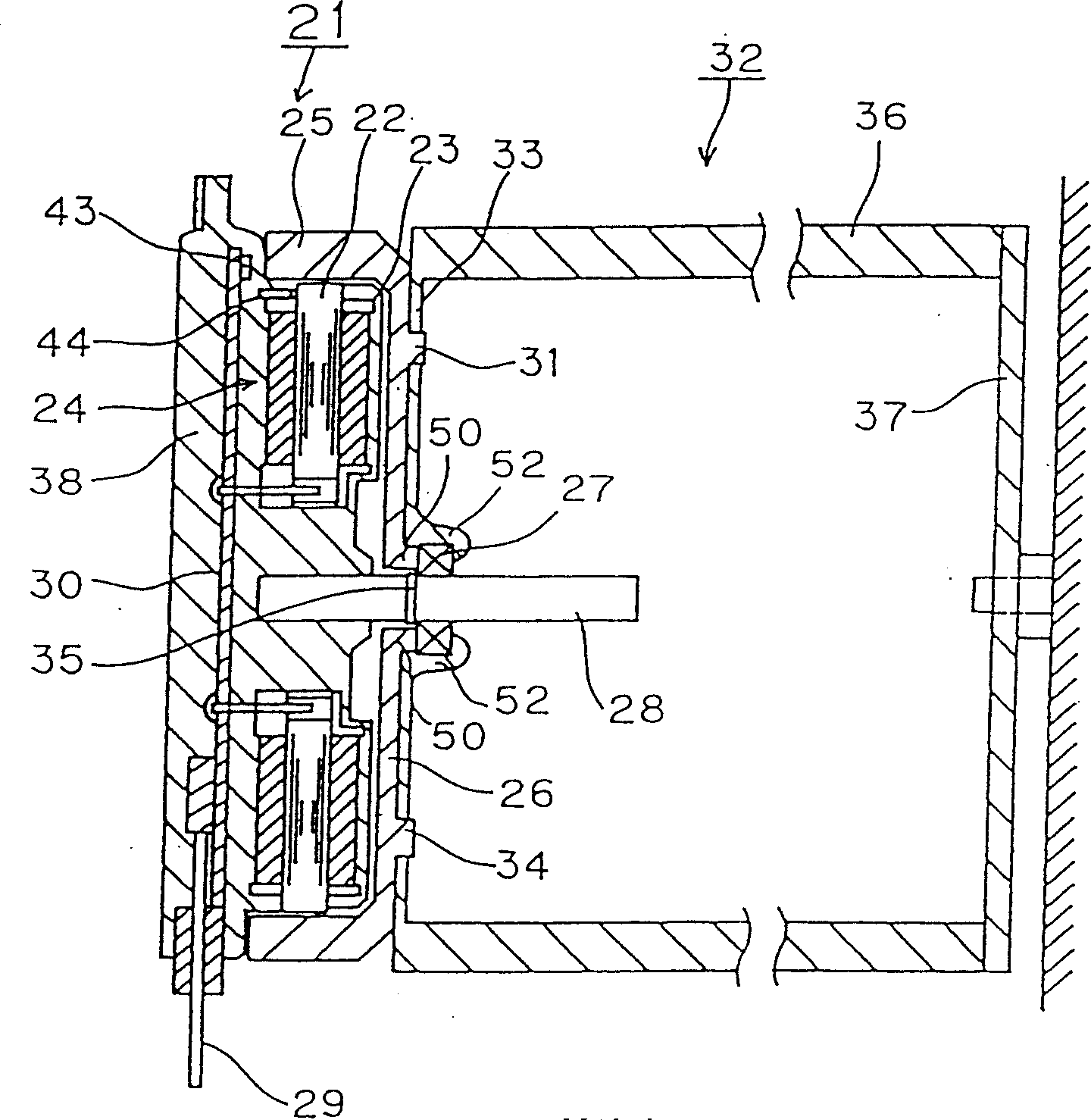
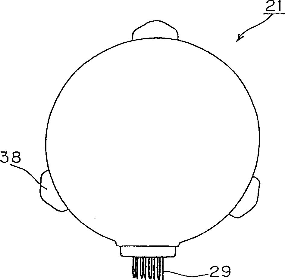
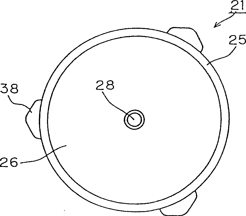
[0056] Figure 1-Figure 3 In order to show the figure of the first embodiment of the present invention, figure 1 It is a cross-sectional view of the thin outer rotor type brushless DC motor (hereinafter referred to as the motor) 21 of the present embodiment, figure 2 is the left side view of the motor 21, image 3 It is the right side view of the motor 21. Below, refer to Figure 1-Figure 3 The configuration of the motor 21 will be described.

[0057] In the motor 21 , a coil 23 is wound around an iron core 22 to form a substantially cylindrical stator 24 .

[0058] On the outside of the stator 24 in the radial direction, a substantially cylindrical rotor 25 composed of permanent magnet pieces and the like is arranged at a distance from the stator 24 . One end in the axial direction of the rotor 25 constitutes a connecting portion 26 extending radially inward, and an annular protrusion 50 is formed at the radially inward end of the connecting portion 26 , that is, near ...

no. 2 Embodiment

[0069] Figure 4 It is a sectional view of the motor 21a of the second embodiment.

[0070] This embodiment is similar to the above-mentioned first embodiment, and the same reference symbols are used for corresponding parts.

[0071] The present embodiment is characterized in that the radial rolling bearing 27 of the first embodiment is replaced by a radial sliding bearing (hereinafter referred to as a sliding bearing) 39 . For this purpose, the base 41 of the substantially hollow truncated cone-shaped holding member 40 made of elastic body (such as hard rubber) is fixed to the rotor radially inwardly of the annular connecting member 33 of the axial flow fan 32. 25 ring-shaped protrusions 50 .

[0072] A concave holding groove 42 is formed along the entire circumference of the holding member 40 in the vicinity of the end on the side opposite to the base 41 . The sliding bearing 39 whose outer peripheral surface has a shape corresponding to the shape of the holding groove 42...

no. 3 Embodiment

[0075] Figure 5 It is a sectional view showing the motor 21b of the third embodiment.

[0076] In the above-mentioned first and second embodiments, the wiring board 30 is arranged on the opposite side of the axial flow fan 32 with respect to the stator 24, but in the present invention, it may be arranged as Figure 5 As shown, the wiring board 30 is arranged on the same side as the axial fan 32 with respect to the stator 24 . Obviously, also in such a modified example, the same operational effects as those described in the above-mentioned first embodiment can be realized.

[0077] That is, also in this embodiment, the same operational effects as those described in the above-mentioned first embodiment can be realized.


PUM


Abstract

A motor 56 is provided with a stator, a supporting shaft fixed to the stator concentrically, a cup-shaped rotor arranged outside virtually in the radial direction with respect to the stator and driven to rotate around the stator, and a rotation support member that is arranged between the supporting shaft and the rotor to support the rotor, in such a way as to be freely rotatable to the support shaft. The axial fan 23, one end of the direction of the axial line of which is fixed, for a room unit 55 of the air conditioner is fixed coaxially with the rotor. Thus the object of the invention is to increase the capability of the room unit of an air conditioner by reducing the number of parts and by shortening the length in the direction of the axial line of a motor.

Description

technical field [0001] The present invention relates to a motor in which a rotor is disposed radially outward of a stator and driven to rotate around the stator, an axial fan using the motor, and an axial fan for an indoor unit of an air conditioner. Background technique [0002] Figure 12 It is a cross-sectional view of a conventional thin outer rotor brushless DC motor (hereinafter referred to as a motor) 1 . Below, refer to Figure 12 The configuration of the motor 1 will be described. [0003] In the motor 1 , a coil is wound around an iron core 2 to form a substantially cylindrical stator 4 . [0004] A substantially cylindrical rotor 5 made of permanent magnet pieces or the like is arranged radially outward of the stator 4 at a distance from the stator 4 . One end portion in the axial direction of the rotor 5 constitutes a connecting portion 6 extending radially inward, and a sleeve 7 is provided integrally with the connecting portion 6 in the hollow portion of the ...

Claims


Application Information

Patent Timeline
Patent Type & Authority Patents(China)
IPC IPC(8): H02K29/08H02K29/00H02K11/00H02K7/14
Inventor 中塚晴雄米谷胜也
Owner NIDEC SHIBAURA CORP
Learn More