
Low-loss frequency scanning antenna planar array based on hybrid feed structure in limited bandwidth

A technology of frequency scanning antenna and limited bandwidth, which is applied in the direction of antenna array, linear waveguide feeding array, specific array feeding system, etc., can solve the problems of large volume and weight, limited application range, low efficiency, etc. Lobe, Efficiency and Gain Improvement, Bandwidth Broadening Effects

Pending Publication Date: 2019-01-11
安徽耀峰雷达科技有限公司
View PDF0 Cites 7 Cited by
  • Summary
  • Abstract
  • Description
  • Claims
  • Application Information

AI Technical Summary

Problems solved by technology

However, the feed network of the frequency scanning antenna needs to adopt a slow wave line structure, which limits its application range due to its large volume and weight, narrow bandwidth and low efficiency

Method used


Image

  • Low-loss frequency scanning antenna planar array based on hybrid feed structure in limited bandwidth
  • Low-loss frequency scanning antenna planar array based on hybrid feed structure in limited bandwidth
  • Low-loss frequency scanning antenna planar array based on hybrid feed structure in limited bandwidth

Examples


Embodiment Construction

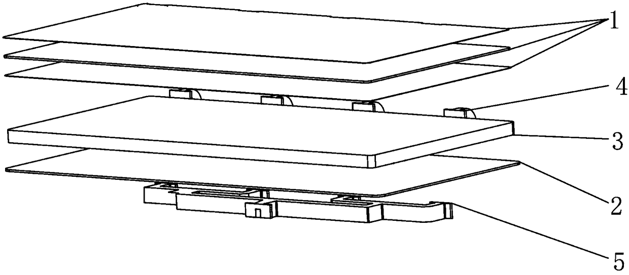
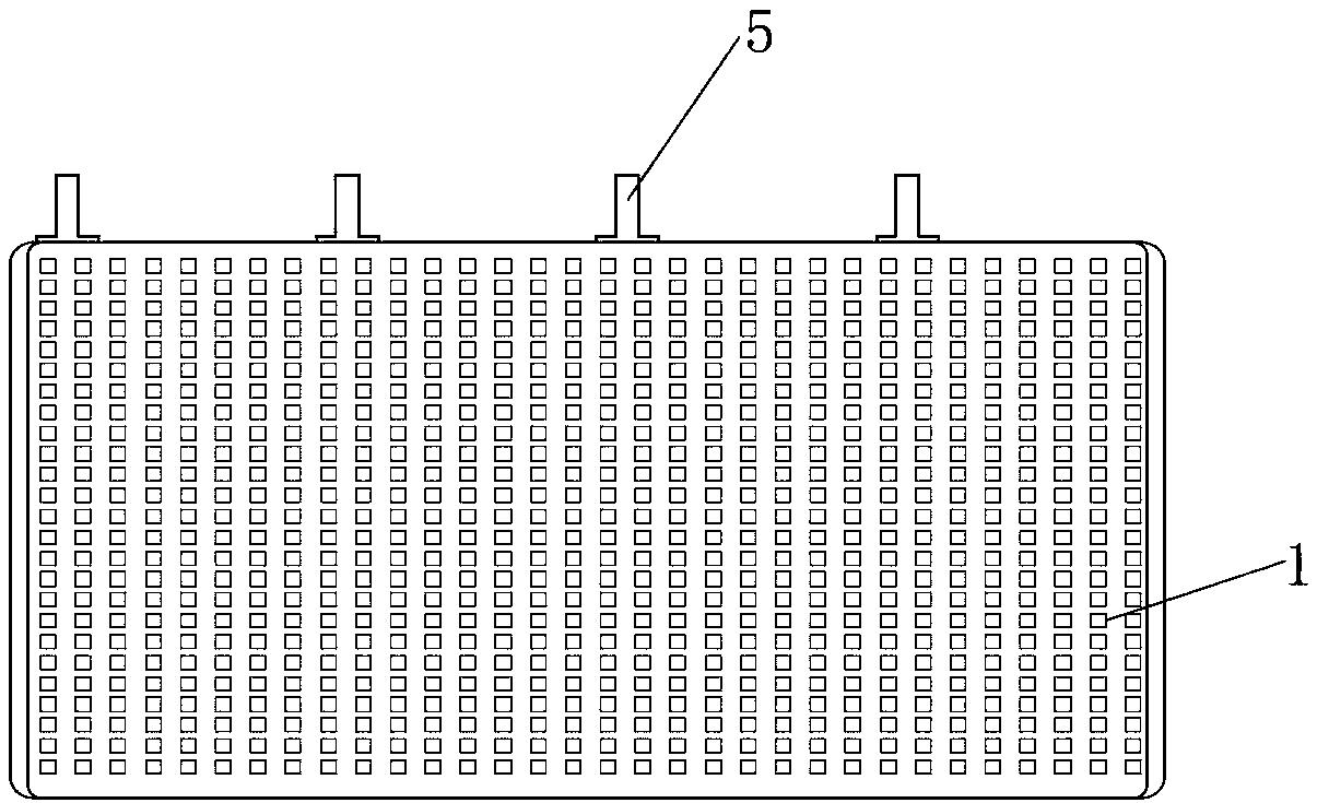
[0027] The following will clearly and completely describe the technical solutions in the embodiments of the present invention with reference to the accompanying drawings in the embodiments of the present invention. Obviously, the described embodiments are only some, not all, embodiments of the present invention. Based on the embodiments of the present invention, all other embodiments obtained by persons of ordinary skill in the art without making creative efforts belong to the protection scope of the present invention.

[0028] see Figure 1-11 , the present invention provides technical solutions:

[0029] A low-loss frequency scanning antenna planar array based on a hybrid feed structure within a limited bandwidth of the present invention, including a double-layer microstrip patch layer 1, a metal floor 2, an E-plane curved waveguide slow wave structure 3, and a 180° waveguide elbow and 4 waveguide power dividers 5; the E-plane curved waveguide slow-wave structure 3 of the f...


PUM


Abstract

The invention discloses a low-loss frequency scanning antenna plane array based on a hybrid feeding structure in a limited bandwidth. The frequency scanning array is composed of a plurality of parallel subarrays, including a double-layer microstrip patch array, a metal floor, an E-plane bent waveguide, a waveguide slot and a microstrip line electromagnetic coupling feeding structure, a waveguide power splitter and a 180-degree elbow, wherein one end of the E-plane bent waveguide is a feeding port, the other end is a waveguide port connected with a matching load, and the sub-array is fed by anE-plane waveguide power splitter; a metal floor with an elliptical slot is placed on an E-plane waveguide, a microstrip line is arranged at a position corresponding to each slot on a dielectric substrate to form an electromagnetic coupling feeding structure, and two sides of each microstrip line are respectively connected with a microstrip transmission line, and ports of the microstrip transmission line are respectively connected with corresponding microstrip patch units. The invention significantly broadens the bandwidth, reduces the loss of the frequency scanning slow wave line, improves theefficiency and the gain of the array, and improves the performance of the frequency scanning antenna.

Description

technical field [0001] The invention relates to the technical field of frequency scanning antennas, in particular to a low-loss frequency scanning antenna planar array based on a hybrid feed structure within a limited bandwidth. Background technique [0002] As one of the radars used in the radar air detection system, the low-altitude detection radar will develop with the development of radar technology, and gradually appear the trend of fusion with other radars. As a result, low-altitude detection is a severe test for the current radar air detection system. The key issue of modern aerial detection stations is how to resist low-altitude penetration and form a relatively complete low-altitude detection capability. In order to discover and detect low-altitude, especially ultra-low-altitude, high-speed invading anti-ship missiles, it is necessary to solve the problem of long-range detection targets. Therefore, low-altitude detection radar usually needs to have strong anti-gro...

Claims


Application Information

Patent Timeline
IPC IPC(8): H01Q1/38H01Q1/48H01Q1/50H01Q21/00
CPCH01Q1/38H01Q1/48H01Q1/50H01Q21/0006H01Q21/0037H01Q21/0075
Inventor 徐文文王昊
Owner 安徽耀峰雷达科技有限公司
Learn More