A battery mounting device for an electric vehicle

A battery installation device, electric vehicle technology, applied in electric vehicles, electric power devices, power devices and other directions, can solve the problems of heavy weight, troublesome installation and disassembly, large battery volume, etc., and achieve the effect of convenient maintenance

Inactive Publication Date: 2019-01-11
XIHUA UNIV
View PDF0 Cites 14 Cited by
  • Summary
  • Abstract
  • Description
  • Claims
  • Application Information

AI Technical Summary

Problems solved by technology

[0002] With the development of society, the popularity of new energy vehicles is getting higher and higher, and the utilization rate of electric vehicles in new energy vehicles occupies a dominant position. The batteries of some large electric vehicles are larger in size and heavier in weight. Under the floor, when installing, you need to raise the car floor first, and then install the battery box. Due to the large volume of the battery box, it is more troublesome to install and disassemble.

Method used


Image

  • A battery mounting device for an electric vehicle
  • A battery mounting device for an electric vehicle
  • A battery mounting device for an electric vehicle

Examples


Embodiment 1

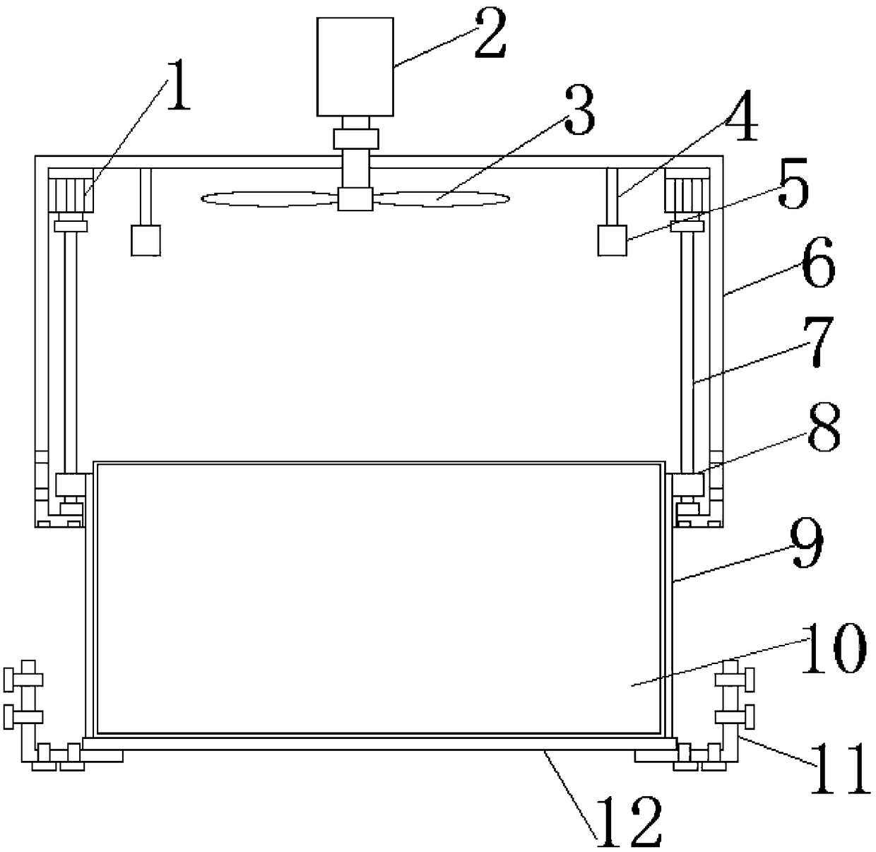
[0022] see Figure 1~2 , a battery installation device for electric vehicles, comprising a first motor 1, a second motor 2, a fan body 3, a fixed rod 4, a fixed frame 5, a mounting box 6, a screw rod 7, a nut seat 8, a lifting box 9, a battery Box 10, mounting bracket 11 and sealing support plate 12, the first motor 1 is installed at the four corner positions of the top plate bottom surface of the installation box 6, and the rotating shaft of the first motor 1 is fixedly connected with a shaft coupling and a screw rod 7 at one end , the screw mandrel 7 is vertically arranged, and the other end of the screw mandrel 7 is fixed on the corner of the base plate top surface of the installation box 6 with a fixed bearing, the screw mandrel 7 is equipped with a nut seat 8, and the screw mandrel 7 and the nut seat 8 above it Threaded connection, the four nut seats 8 inside the installation box 6 are fixedly connected to the top ends of both sides of the lift box 9 respectively, the fro...

Embodiment 2

[0025] see Figure 5-10 A type of battery pack is fixed inside the battery box 10, and the type of battery pack includes two opposite circular connection plates 1-1-11, and a through hole is provided in the middle of the connection plate 1-1-11 A plurality of concentric circular grooves 1-1-12 are arranged on the opposite end surfaces of the two connecting plates 1-1-11, and the two ends of the cylindrical heat sink 1-1-14 are respectively inserted into the two circular connecting plates In the groove 1-1-12 of 1-1-11; the bottom of the groove is provided with a strip-shaped guide hole, and the end of the heat sink 1-1-14 is provided with a protruding strip-shaped guide piece, and the guide piece passes through into the guide hole; the guide hole communicates with the water guide hole 1-1-13 arranged along the radial direction on the side wall of the circular connecting plate 1-1-11; a seal is set between the guide piece and the inner surface of the guide hole ring or apply s...

Embodiment 3

[0030] see Figure 3-4 , the battery box 10 is fixed with a second-type battery pack, the second-type battery pack is a rectangular parallelepiped shape formed by contacting the two sides of a plurality of batteries, and the second-type battery pack is placed in a cooling box suitable for its shape In the body 2-10, the cooling box 2-10 includes a ventilation casing 2-11 with openings on the top and bottom, and a honeycomb support 2-12 is arranged inside the ventilation casing 2-11, and the diamond-shaped space of the support 2-12 is The battery 1-1-18 is inserted inside, and the bottom of the bracket 2-12 is connected with the upper surface of the stop plate 2-13 by snapping or bonding, and the upper surface of the stop plate 2-13 is connected with the battery 1-1-18 A through ventilation hole is provided at the contact position.


PUM


Abstract

A battery mounting device for electric vehicle disclosed in the invention includes a first motor, Second motor, Fan body, fixing bar, Installation box, screw, Nut holder, lifting box, Battery case, mounting bracket and seal support plate. A first motor is installed at four corner positions on the bottom surface of the top plate of the mounting box, the rotating shaft of the first motor is fixedlyconnected with one end of the screw rod by a coupling. As that screw rod is driven to rotate by the first motor. As that screw rod transmission principle is use for controlling the rise or fall of thenut seat, so as to control the rise or fall of the lifting box, so as to control the ascending and descending of the battery box in the lifting box. The battery box can be self-unloaded, and the installation, disassembly and maintenance of the battery box are more convenient. The sealing support plate is fixed and stable by using the mounting bracket, the battery box is avoided to sway up and down when the vehicle is bumpy by using the fixing bracket, and the fan body is driven to rotate by the second motor, so as to cool the battery.

Description

technical field [0001] The invention relates to the field of batteries, in particular to a battery installation device for electric vehicles. Background technique [0002] With the development of society, the popularity of new energy vehicles is getting higher and higher, and the utilization rate of electric vehicles in new energy vehicles occupies a dominant position. The batteries of some large electric vehicles are larger in size and heavier in weight. Under the bottom plate, when installing, it is necessary to raise the car bottom plate first, and then install the battery box. Due to the large volume of the battery box, it is more troublesome to install and disassemble. Contents of the invention [0003] The object of the present invention is to provide a battery installation device for an electric vehicle to solve the problems raised in the above-mentioned background technology. [0004] To achieve the above object, the present invention provides the following techni...

Claims


Application Information

Patent Timeline
Patent Type & Authority Applications(China)
IPC IPC(8): H01M2/10H01M2/20H01M10/613H01M10/625H01M10/6551H01M10/6556H01M10/6563H01M10/6568B60K1/04B60L58/26H01M50/244H01M50/249H01M50/258H01M50/264H01M50/502
CPCH01M10/613H01M10/625H01M10/6551H01M10/6556H01M10/6563H01M10/6568B60K1/04B60K2001/0455H01M2220/20H01M50/20H01M50/502Y02T10/70Y02E60/10
Inventor 陈子龙
Owner XIHUA UNIV
Why Eureka
Try Eureka