Eureka AIR delivers breakthrough ideas for toughest innovation challenges, trusted by R&D personnel around the world.

An organic electroluminescent device

An electroluminescent device, organic technology, applied in the direction of electric solid devices, electrical components, semiconductor devices, etc., can solve the problem of low light extraction efficiency, achieve high luminous efficiency, improve light extraction efficiency, weaken surface plasmon effect and waveguide effect Effect

Active Publication Date: 2019-01-11
CHANGCHUN HYPERIONS TECH CO LTD
View PDF4 Cites 6 Cited by
  • Summary
  • Abstract
  • Description
  • Claims
  • Application Information

AI Technical Summary

Problems solved by technology

[0004] Purpose of the invention: In view of the above problems, the purpose of the present invention is to provide an organic electroluminescent device, which solves the problem of low light extraction efficiency of the current organic electroluminescent device

Method used


Image

  • An organic electroluminescent device
  • An organic electroluminescent device
  • An organic electroluminescent device

Examples


Embodiment 1

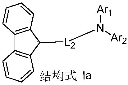
[0126] Synthesis Example 1: Preparation of Compound Ia-2

[0127]

[0128] Into the round bottom flask, add the compounds bis(4-biphenyl)amine (23.7g, 73.8mmol), p-bromoiodobenzene (20.8g, 73.8mmol), t-BuONa (10.7g, 111mmol), Pd(OAc ) 2 (0.33g, 1.47mmol) and ultrasonically deoxygenated toluene (1.5L), refluxed overnight under nitrogen protection, treated the reaction solution with ethyl acetate and water after cooling, and the obtained organic layer was washed with MgSO 4 After drying, the solvent was evaporated under reduced pressure, and column chromatography was performed with silica gel as the stationary phase and dichloromethane / hexane as the eluent to obtain compound A1 (27.4 g, 78%).

[0129] Compound A1 (23.8g, 50mmol) was added to a round bottom flask, and then an appropriate amount of anhydrous THF was added to dissolve it. At a temperature of -78°C, n-BuLi (4.9ml, 60mmol) was added dropwise to the reaction flask , After reacting for 0.5h, trimethyl borate (7.8g...

Embodiment 2

[0132] Synthesis Example 2: Preparation of Compound Ia-10

[0133]

[0134] In the preparation method of compound Ia-2 in Synthesis Example 1, bis(4-biphenyl)amine was replaced with equimolar compound C1, and other steps were the same to obtain compound Ia-10, (14.7g, 77% ). Mass spectrum m / z: theoretical value: 635.81; found value: 635.23. Theoretical element content (%)C 49 h33 N: C, 92.57; H, 5.23; N, 2.20; Measured element content (%): C, 92.53; H, 5.29; N, 2.18. The above results confirmed that the obtained product was the target product.

Embodiment 3

[0135] Synthesis Example 3: Preparation of Compound Ia-18

[0136]

[0137] In the preparation method of compound Ia-2 in Synthetic Example 1, bis(4-biphenyl)amine was replaced by equimolar compound C2, and other steps were the same to obtain compound Ia-18, (14.8g, 82% ). Mass spectrum m / z: theoretical value: 601.79; found value: 601.22. Theoretical element content (%)C 46 h 35 N: C, 91.81; H, 5.86; N, 2.33; Measured element content (%): C, 91.79; H, 5.90; N, 2.31. The above results confirmed that the obtained product was the target product.


PUM


Abstract

The invention discloses an organic electroluminescent device, which relates to the technical field of organic electroluminescent display. The organic electroluminescent device including an anode, an organic layer, a cathode and a light extraction layer, the organic layer is located between the anode and the cathode. The light extraction layer is located on a side of the cathode away from the anode, the light extraction layer sequentially comprising a first light extraction layer and a second light extraction layer from a side close to the cathode, the first light extraction layer containing acompound represented by Structural Formula Ia, and the second light extraction layer containing a compound represented by Structural Formula I. The organic electroluminescent device of the invention not only improves the transmittance of the cathode surface, but also greatly reduces the influence of the surface plasma effect and the waveguide effect, and improves the light-emitting efficiency of the organic electroluminescent device because of the low light absorption coefficient and the high refractive index of the materials used in the first light-emitting layer and the second light-emittinglayer.

Description

technical field [0001] The invention relates to the technical field of organic electroluminescence display, in particular to an organic electroluminescence device. Background technique [0002] Organic Light-Emitting Diode (OLED) refers to a device in which organic photoelectric materials emit light under the action of current or electric field, which can directly convert electrical energy into light energy. In recent years, OLED as a new generation of flat panel display and solid-state lighting technology is receiving more and more attention. Compared with liquid crystal display technology, OLED is more and more used in the field of display and lighting due to its low power consumption, active light emission, fast response speed, high contrast, no viewing angle limitation, and flexible display. [0003] However, due to the effect of waveguide effect and surface plasmon effect on OLED, only about 20% of the light can escape from the device, and the remaining about 80% of th...

Claims


Application Information

Patent Timeline
IPC IPC(8): H01L51/00H01L51/54
CPCH10K85/622H10K85/624H10K85/626H10K85/636H10K85/633H10K85/615H10K85/631H10K85/654H10K85/6574H10K85/342H10K85/6572
Inventor 蔡辉孙敬
Owner CHANGCHUN HYPERIONS TECH CO LTD
Why Eureka
Eureka Blog
Learn More