


Quick Research
Generate reliable direction feasibility study reports for your R&D in just a few steps.

Technical Q&A
Discover and master advanced knowledge NOW. Basics, ideas, possibilities, all at once.

Find Solutions
As an expert in R&D theories, this can generate solutions to your technical problems instantly.

Evaluate Feasibility
Analyze your overall solution with one click, know your potential R&D risks in advance.

Monitor Landscape
Get weekly tech updates, stay abreast of the latest tech innovations and key insights.
An LED light-emitting device for repair and regeneration of retinal cells and application thereof
A technology of retinal cells and light-emitting devices, applied in semiconductor devices, electrical components, circuits, etc., can solve the problems of lack of far-red light, reduce the harm of blue light, and improve the health of eyesight
- Summary
- Abstract
- Description
- Claims
- Application Information
AI Technical Summary
Problems solved by technology
Method used
Image


Examples
Embodiment 1
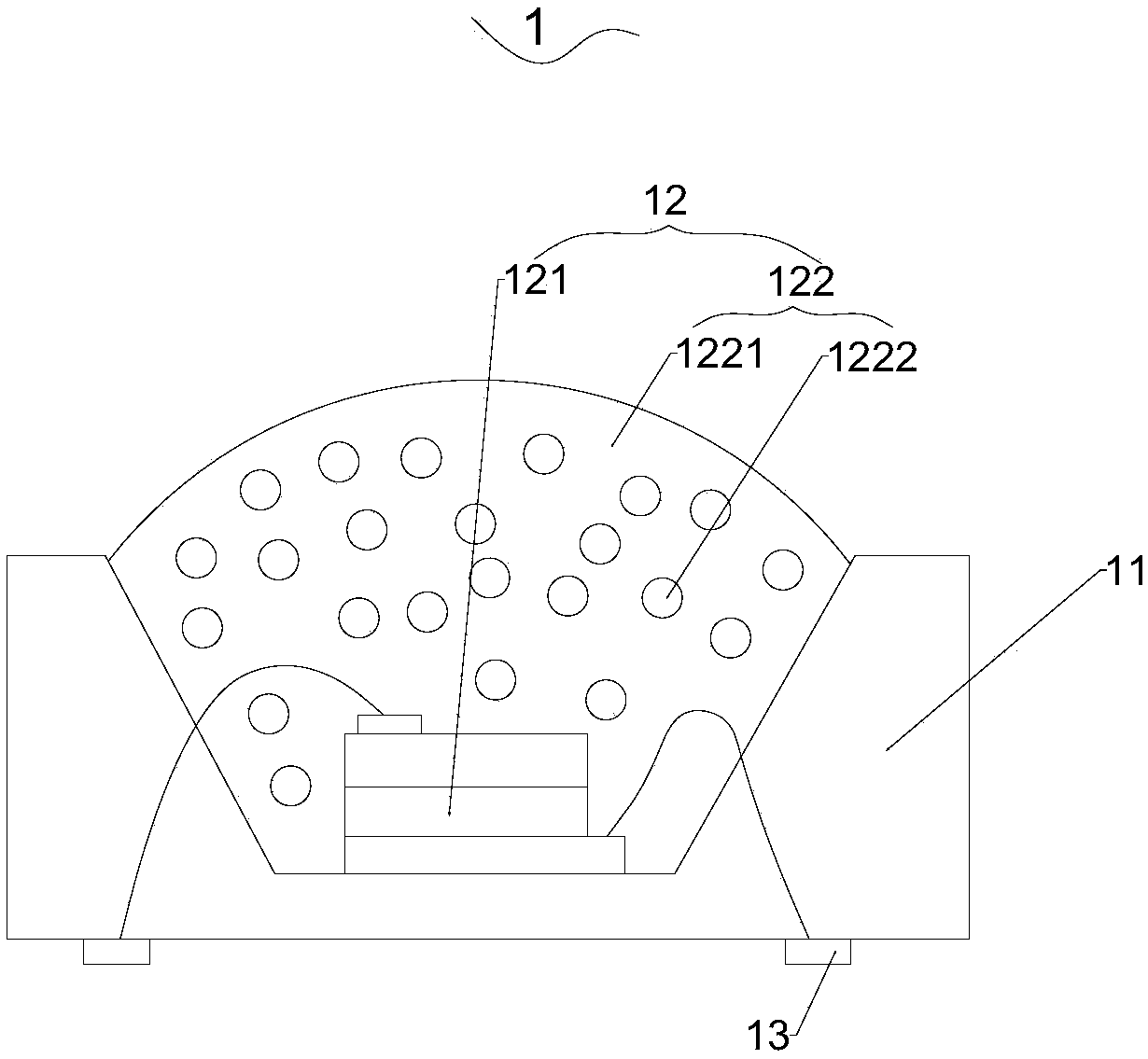
[0044] Such as figure 1 Shown is a schematic diagram of the specific structure of the LED device described in this embodiment. In this embodiment, both the base 11 and the LED chip 121 are purchased from Guangdong Jinko Electronics Co., Ltd.
[0045] refer to figure 1 A recessed accommodation groove is formed on the base 11, an electrode 13 is provided on the end surface of the base 11 facing away from the accommodation groove, the LED chip 121 is fixed at the bottom of the accommodation groove, and the LED chip 121 connects with the electrode through a wire. 13 electrical connection. After mixing red phosphor powder, far red phosphor powder and AB transparent silica gel, vacuum defoaming, and then use a dispenser to drop it onto the side of the LED chip 121 facing the outside of the base 11, in a vacuum state, After being baked and cured at 150°C, an LED light-emitting device capable of independently emitting light under direct current drive is formed.
[0046] Red phospho...
Embodiment 2
[0052] The difference between this embodiment and Embodiment 1 is that the far-red phosphor adopts Y 3 Al 5 o 12 As a luminescent matrix, the far-red phosphor is prepared by the following method: with Y 2 o 3 、Al 2 o 3 and Cr 2 o 3 As a raw material, add a co-solvent to it, put it into a corundum crucible after ball milling and mixing, and then calcinate in a muffle furnace at a high temperature of 1250-1650 ° C. After the reaction is completed, it can be crushed.
[0053] Cr above 2 o 3 as Cr 3+ Cr(NO 3 ) 3 Instead, the co-solvent can use BaF 2 , AlF 3 or H 3 BO 3 , According to the amount of raw materials, the calcination time is 2-10h.
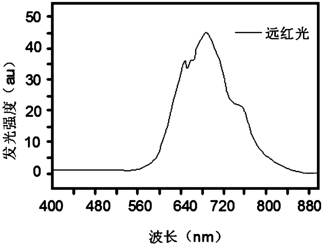
[0054] The LED light-emitting device prepared in this embodiment was energized, and collected data such as image 3 The spectrum shown shows that its wavelength is between 570-850nm.
[0055] It should be noted that the far-red phosphor in this embodiment can also be replaced by other high-symmetry oxides with garnet struc...
Embodiment 3
[0057] The difference between the present embodiment and the third embodiment is that the red light phosphor in the present embodiment adopts Ba 1.5 Al 5 N 8 o 0.5 , the far-red phosphor uses Sr 3 SiO 4 fo. The Ba 1.5 Al 5 N 8 o 0.5 and Sr 3 SiO 4 The preparation methods of FO are conventional methods, which will not be repeated here.
[0058] The LED light-emitting device prepared in this embodiment was energized, and collected data such as Figure 4 The spectrum shown shows that its wavelength is between 570-850nm.
PUM
| Property | Measurement | Unit |
|---|---|---|
| Wavelength | aaaaa | aaaaa |
Abstract
Description
Claims
Application Information
 - R&D Engineer
- R&D Manager
- IP Professional
- Industry Leading Data Capabilities
- Powerful AI technology
- Patent DNA Extraction
Browse by: Latest US Patents, China's latest patents, Technical Efficacy Thesaurus, Application Domain, Technology Topic, Popular Technical Reports.
© 2024 PatSnap. All rights reserved.Legal|Privacy policy|Modern Slavery Act Transparency Statement|Sitemap|About US| Contact US: help@patsnap.com