
Magnetic gradiometer with adjustable baseline distance of sensor array

A sensor array and baseline distance technology, applied in the field of magnetic target detection, can solve the problems of magnetic gradiometers not being flexible enough, not wide enough, and large detection errors, etc., to achieve convenient and rapid deployment and storage, and enhance flexibility and applicability , the effect of reducing the misalignment error

Active Publication Date: 2019-01-11
HARBIN INST OF TECH
View PDF18 Cites 0 Cited by
  • Summary
  • Abstract
  • Description
  • Claims
  • Application Information

AI Technical Summary

Problems solved by technology

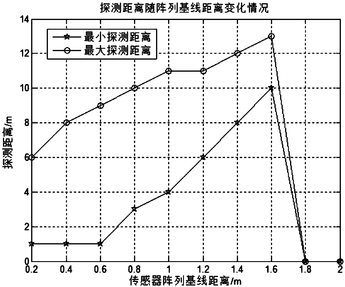
[0004] 1. The baseline of the magnetic sensor array is fixed. Under the required detection accuracy, the detection range is fixed, lacks flexibility, and is not widely applicable.
[0005] At present, the baseline distance of the sensor array of the magnetic gradiometer used at home and abroad is mostly fixed, and the detection range of the gradiometer is determined and cannot be changed.
If the magnetic target is too far or too close at this time, the detection error will be very large, which cannot meet the detection accuracy requirements
If you want to detect at this time, you need to redesign the baseline distance of the magnetic sensor array and remake the magnetic gradiometer, wasting a lot of time and cost
Such a magnetic gradiometer is not flexible enough, and its applicability is not strong
[0006] 2. The magnetic gradiometer cannot correct the misalignment error on the mechanical structure, and the method of correcting the misalignment error by obtaining the error parameters requires expensive cost
However, the above method requires a high-precision magnetic field generator to generate a magnetic field with a stable amplitude, and at the same time to generate a uniform magnetic field that can cover the entire measurement structure, which is very expensive.

Method used


Image

  • Magnetic gradiometer with adjustable baseline distance of sensor array
  • Magnetic gradiometer with adjustable baseline distance of sensor array
  • Magnetic gradiometer with adjustable baseline distance of sensor array

Examples


Embodiment Construction

[0030] The present invention will be described in further detail below in conjunction with the accompanying drawings: the present embodiment is implemented on the premise of the technical solution of the present invention, and detailed implementation is provided, but the protection scope of the present invention is not limited to the following embodiments.

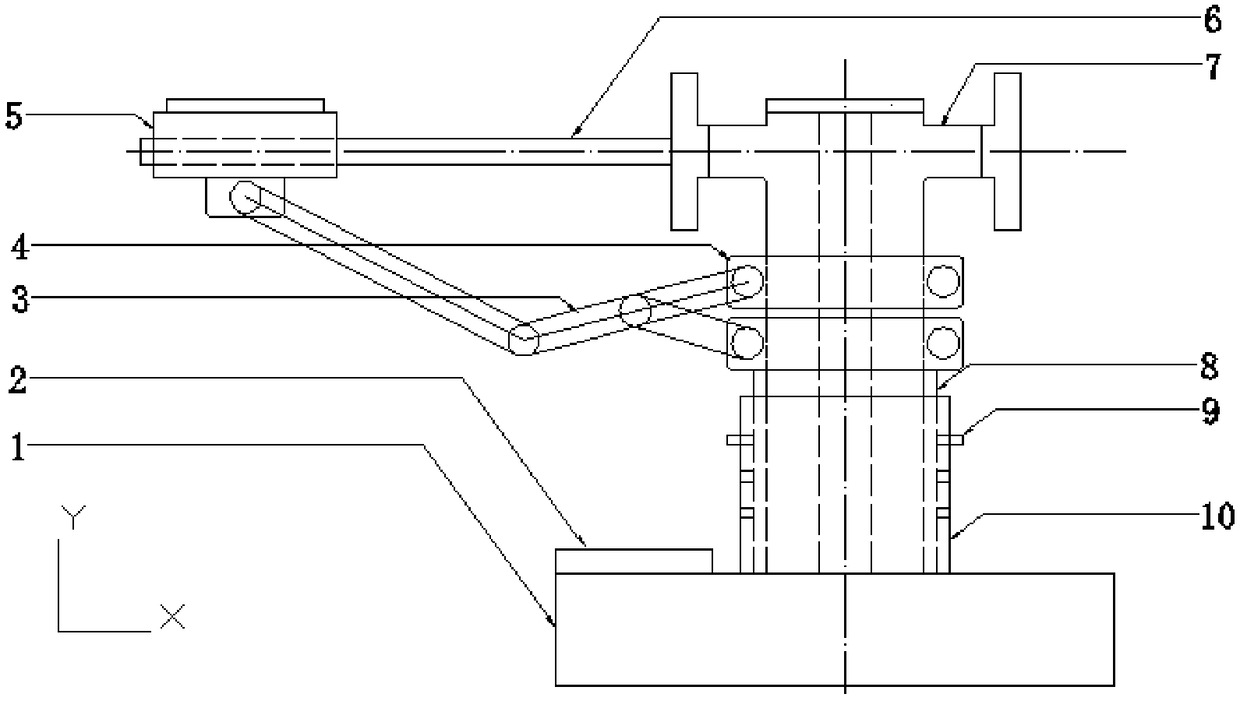
[0031] Such as image 3 As shown, a magnetic gradiometer with an adjustable sensor array baseline distance involved in this embodiment includes a base 1, a main control board 2, a hollow connecting rod 3, a fixed slip ring 4, a sensor adjustment device a5, and a horizontal guide rod 6 , the main shaft 7, the inner sleeve 8, the spring pin 9, the outer sleeve 10, the outer edge of the base 1 is provided with the main control board 2, the central position of the base 1 is fixedly installed with the outer sleeve 10, and the outer sleeve 10 is placed Inside the inner sleeve 8, the main shaft 7 is installed inside the inner sle...


PUM


Abstract

The invention provides a magnetic gradiometer with an adjustable baseline distance of a sensor array, and mainly solves the problems that a traditional magnetic gradiometer is not flexible enough andnot high in applicability. The magnetic gradiometer with the adjustable baseline distance of the sensor array can rotate around three degrees of freedom to adjust the position of the magnetic sensor after the magnetic sensor is installed. Through multiple measurements and adjustments, misalignment errors of the measurement structure can be accurately calibrated. The aim of reducing the costs of anexperiment while accurately calibrating the misalignment errors of the magnetic gradiometer is achieved. The invention is a magnetic gradiometer that can be used to design a three-dimensional sensorarray such as a regular hexahedron with an adjustable baseline distance. At the same time, a magnetic gradiometer that makes a sensor array as a unit for structural expansion, and can be used for designing the cooperative use of multiple sensor arrays is provided.

Description

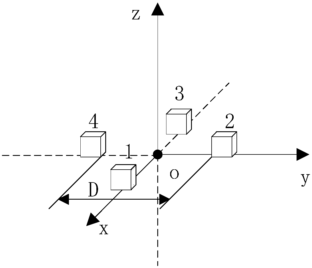
technical field [0001] The invention relates to a magnetic gradiometer with adjustable baseline distance of a sensor array, which belongs to the field of magnetic target detection. Background technique [0002] The application field of magnetic target detection using magnetic gradiometer is very wide, and it has been paid more and more attention and researched by more and more people. In the field of medical research, it can be used for capsule endoscope positioning, tumor positioning, surgical robot navigation, magnetic brain research, etc.; in the field of geophysics, it can be used for cave mapping, oil and gas and mineral exploration, archaeological exploration, and earth magnetic field monitoring; in military In the field of engineering, it can be used for submarine detection, ship detection, unexploded ordnance detection, etc. The working principle of the magnetic gradiometer is to form an array of several magnetic sensors, and post-processing after data collection. ...

Claims


Application Information

Patent Timeline
Patent Type & Authority Applications(China)
IPC IPC(8): G01R33/022
CPCG01R33/0023G01R33/0094G01R33/022
Inventor 潘东华林生鑫葛宇航李吉刘添豪宋凯李立毅
Owner HARBIN INST OF TECH
Learn More