Compact track two-dimensional and three-dimensional imaging system

A three-dimensional imaging, compact technology, applied in the direction of measuring devices, material analysis through optical means, instruments, etc., to reduce weight, adapt to a wide range, and ensure the effect of two-dimensional imaging

Pending Publication Date: 2019-01-11
成都精工华耀科技有限公司
View PDF3 Cites 5 Cited by
  • Summary
  • Abstract
  • Description
  • Claims
  • Application Information

AI Technical Summary

Problems solved by technology

[0005] In order to solve the above-mentioned problems existing in the existing track inspection method, the present invention provides a compact track two-dimensional and three-dimensional imaging system

Method used


Image

  • Compact track two-dimensional and three-dimensional imaging system
  • Compact track two-dimensional and three-dimensional imaging system
  • Compact track two-dimensional and three-dimensional imaging system

Examples


Embodiment 2

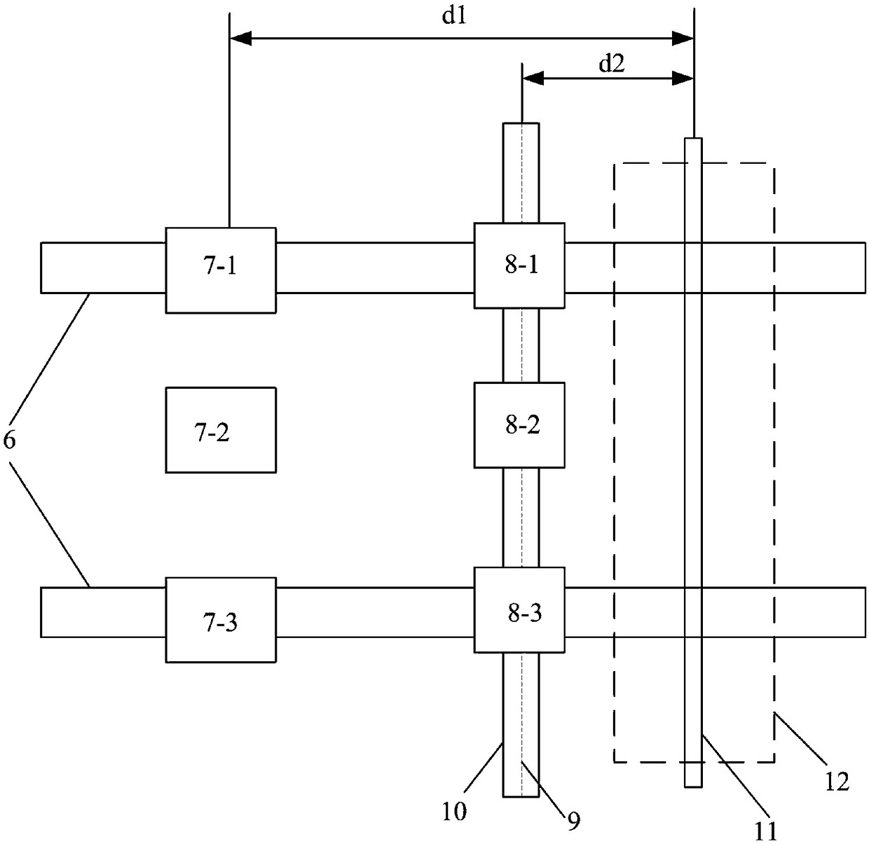
[0044] The 3D imaging unit, the slice light P2 and the line array imaging unit, the slice light P1 are sequentially arranged longitudinally along the track. Such as figure 2 As shown, the 3D imaging unit is composed of three 3D cameras 7, and the three 3D cameras are arranged vertically along the longitudinal direction of the track, wherein the 3D cameras 7-1 and 7-3 are located directly above the rail, and the 3D camera 7-2 is located directly above the center of the rail , the imaging field of view of the 3D cameras has overlapping areas to perform 3D imaging on the entire track; the angle between the optical axes of the three 3D cameras 7 and the sheet light PI is 45 degrees, and the optical centers of the 3D cameras 7 extend along the track to the sheet light PI The distance of P1 is d1, and the value of d1 is 500mm; the line array imaging unit is composed of three line array cameras 8, wherein the line array cameras 8-1 and 8-3 are located directly above the rail, and th...

Embodiment 3

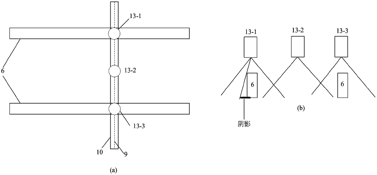
[0051] The difference from Example 2 is that, as Figure 5 As shown, the sheet light P2 is composed of five line light sources 13 collinearly spliced ​​together, wherein the line light sources 13-1, 13-2, 13-4, and 13-5 are respectively located on both sides above the rail, and 13-3 is located above the center of the track ;Such as Figure 6 As shown, the sheet light P1 is composed of 5 linear structured light generators 14 co-linearly spliced ​​together, of which 4 linear structured light generators 14-1, 14-2, 14-4, 14-5 are respectively located on both sides above the rail , a line structured light generator 14-3 is located above the center of the track. The advantage of this is that if Figure 4 As shown, in the sheet light P2 in Embodiment 2, when the line light source 13-1 or 13-3 is located directly above the rail, shadows will be generated due to the obstruction of the rail. Similarly, for the sheet light P1 in Embodiment 2, when the line structured light generators...

Embodiment 4

[0053] The difference from Embodiment 3 is that the light sheets P1 and P2 are near-infrared light sources with a wavelength of 808nm, and an 808nm narrow-band filter is installed at the front end of the line array camera 8 and 3D camera 7.


PUM

PropertyMeasurementUnit
widthaaaaaaaaaa
thicknessaaaaaaaaaa
thicknessaaaaaaaaaa

Abstract

For acquiring two-dimensional images and three-dimensional morphology data required for visual inspection of tracks, the invention discloses a compact track two-dimensional and three-dimensional imaging system. The system consists of a sheet light generator, a linear array imaging unit, a 3D imaging unit, a supporting device and a shell, wherein the sheet light generator generates two beams of sheet light by splicing a plurality of light sources, and provides illumination for the linear array imaging unit and the 3D imaging unit. The linear array imaging unit and the 3D imaging unit perform linear array scanning imaging and three-dimensional scanning in a longitudinal direction of a track to acquire a two-dimensional image and three-dimensional morphology data of the surface of the track.Further, the linear array imaging unit and the sheet light generator are integrated, and the length of the 3D imaging unit is reduced by adopting a light path folding method, so that the length of theimaging system in the track direction is reduced, and the compact track two-dimensional and three-dimensional imaging system is provided.

Description

technical field [0001] The invention relates to equipment in the field of railway infrastructure detection, in particular to a compact track two-dimensional and three-dimensional imaging system. Background technique [0002] The railway is the main artery of national transportation, and it plays a major role in many fields such as national economy, national travel, and national defense transportation. The track is the infrastructure of railway transportation, and the track is composed of a ballast bed system, a rail system, and a fastener system. During the long-term operation of the track, the rail system will have defects such as cracks and cracks, the fastener system will have defects such as bolt looseness, spring strip breakage, and spring strip drop-off, and the ballast bed system will have defects such as cracks and fractures. In the subway, the track bed system also has problems such as foreign objects in the track bed (items missed by passengers: mobile phones, wat...

Claims


Application Information

Patent Timeline
Patent Type & Authority Applications(China)
IPC IPC(8): G01N21/88G01N21/01
CPCG01N21/01G01N21/8806G01N21/8851G01N2021/8887G01N2021/0112
Inventor 左丽玛其他发明人请求不公开姓名
Owner 成都精工华耀科技有限公司
Why Eureka
Try Eureka