
Compression test method for honeycomb SCR catalyst

A technology of SCR catalyst and testing method, which is applied in the field of compressive testing of honeycomb SCR flue gas denitrification catalyst, can solve the problems of broken samples, large errors in measurement results, unfavorable sample recovery and disposal, etc., so as to avoid broken and maintain Integrity, effect of saving stakeout time

Inactive Publication Date: 2019-01-11
GUODIAN ENVIRONMENTAL PROTECTION RES INST CO LTD
View PDF4 Cites 2 Cited by
  • Summary
  • Abstract
  • Description
  • Claims
  • Application Information

AI Technical Summary

Problems solved by technology

In the process of anti-pressure detection of finished catalyst products, the commonly used detection devices are mainly anti-pressure detection devices in the construction / cement industry. The current method has the following problems in the actual use process: 1) The measurement mode is based on a constant liter of 1125N / s The pressure rate is used to squeeze the sample until the sample breaks
Due to the instability of the catalyst structure during the rapid pressurization process, it is easy to cause large errors in the measurement results, high degree of dispersion, and poor reproducibility. It is impossible to accurately determine the real mechanical properties of the honeycomb SCR flue gas denitrification catalyst.
2) The detection process leads to the eventual breakage of the catalyst sample, which is a destructive detection method, which is not conducive to the recovery and disposal of the sample. In addition, the test block of the device is a hard test block, and the catalyst is a fragile product, so the test It is necessary to ensure that the test block is complete, which is not conducive to the placement and operation of the catalyst test block.
Therefore, the existing detection methods and devices are difficult or unable to meet the detection requirements of the compressive strength of honeycomb SCR catalysts in coal-fired power plants. It is urgent to develop new testing methods and devices to effectively solve the defects and shortcomings of existing devices.

Method used


Image

  • Compression test method for honeycomb SCR catalyst
  • Compression test method for honeycomb SCR catalyst
  • Compression test method for honeycomb SCR catalyst

Examples


Embodiment

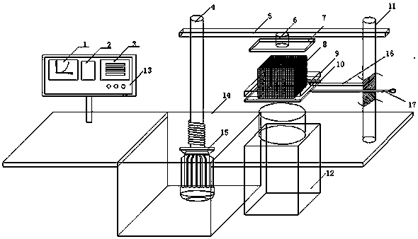
[0025] The structure of the pressure testing machine used in a kind of honeycomb SCR catalyst compression test method of the present embodiment is as follows figure 1 As shown, it includes an industrial computer 13 , a machine platform 14 , a motor 15 , a screw mandrel 4 , a suspension rod 5 , a pressure sensor 6 , an upper platen 7 , a lower platen 10 and a guide post 11 .

[0026] In this embodiment, the motor 15 is arranged in the machine platform 14, the output end of the motor 15 is connected with the screw mandrel 4, and one end of the suspension rod 5 is provided with a threaded hole cooperating with the screw mandrel 4, and the suspension rod 5 is rotatably connected with the screw mandrel 4 through the threaded hole , the other end of the suspension rod 5 is provided with a through hole matched with the guide column 11, the suspension rod 5 is slidably connected with the guide column 11 through the through hole, and one end of the guide column 11 is fixed on the machin...


PUM


Abstract

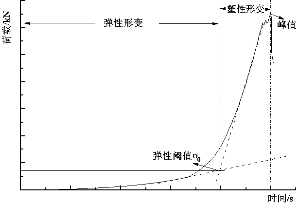
The invention relates to a compression test method for a honeycomb SCR catalyst. According to the method, a pressure test machine is used for extruding a catalyst test block at a constant speed; a pressure sensor on the pressure test machine measures a pressure value of the catalyst test block; a pressure curve is drawn by taking the time as horizontal coordinates and the pressure value as vertical coordinates; the curve is composed of a continuous elastic deformation curve S1 and a brittle deformation curve S2; pressure application is stopped after a peak value appears on the brittle deformation curve S2 in the pressure curve; and then a tangent line L1 and a tangent line L2 of the curves S1 and S2 are drawn, the tangent line L1 and the tangent line L2 are intersected, an intersection point is a threshold point of the catalyst test block, and the threshold point of the catalyst test block is defined as a compressive strength value of the catalyst.

Description

technical field [0001] The invention relates to a compression test method for a honeycomb SCR flue gas denitrification catalyst, which belongs to the field of mechanical performance detection of SCR flue gas denitrification catalysts. Background technique [0002] Catalyst is the core of SCR flue gas denitrification technology, and honeycomb catalyst is a kind of commercial SCR flue gas denitrification catalyst that is widely used at present. The mechanical performance of the catalyst is directly related to the safety and reliability of the SCR flue gas denitrification system, and the compressive strength is a key indicator for judging the mechanical performance of the honeycomb catalyst. In the process of honeycomb catalyst production and quality inspection, it is necessary to carry out sampling inspection of the compressive strength of the finished catalyst, so as to ensure that the mechanical properties of the honeycomb catalyst product meet the actual use requirements. ...

Claims


Application Information

Patent Timeline
IPC IPC(8): G01N3/08
CPCG01N3/08G01N2203/0019
Inventor 黄奎姚杰庄柯金定强沈磊肖正雨白艳周爱奕沙柯燃林正根赵子诚侯深尤晓晨
Owner GUODIAN ENVIRONMENTAL PROTECTION RES INST CO LTD
Learn More