
Construction device of cast-in-place concrete pipe pile and construction method of formed pile

A technology for concrete pipe piles and construction devices, which is applied in the directions of earth-moving drilling, drilling equipment and methods, drilling pipes, etc., can solve the problems of increasing construction costs and increasing the amount of concrete poured into piles.

Pending Publication Date: 2019-01-11
刘守进
View PDF0 Cites 1 Cited by
  • Summary
  • Abstract
  • Description
  • Claims
  • Application Information

AI Technical Summary

Problems solved by technology

In order to increase the bearing capacity of a single pile, it is usually achieved by increasing the pile diameter and lengthening the pile body, which also increases the amount of concrete poured into the pile, resulting in an increase in construction costs

Method used


Image

  • Construction device of cast-in-place concrete pipe pile and construction method of formed pile
  • Construction device of cast-in-place concrete pipe pile and construction method of formed pile
  • Construction device of cast-in-place concrete pipe pile and construction method of formed pile

Examples


Embodiment 1

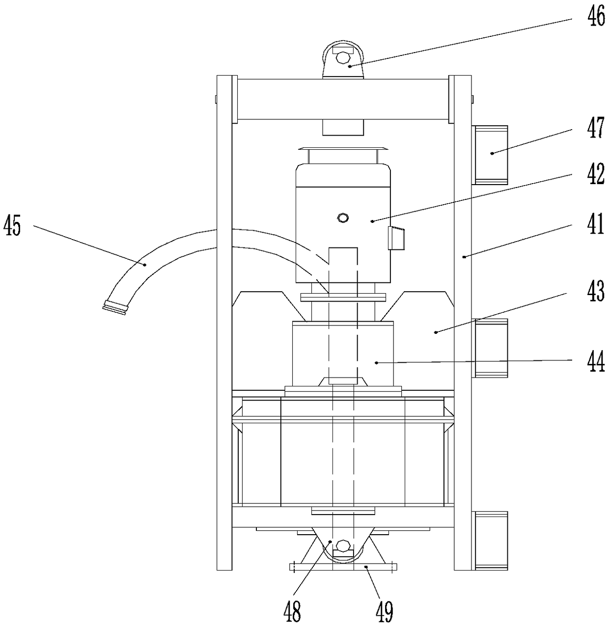
[0047] Such as Figure 1-Figure 11 As shown, the cast-in-place concrete pipe pile construction device is composed of a power head device 40 , a drilling tool reducing device 10 , several standard section drilling tools 20 and a bottom section drilling tool 30 .

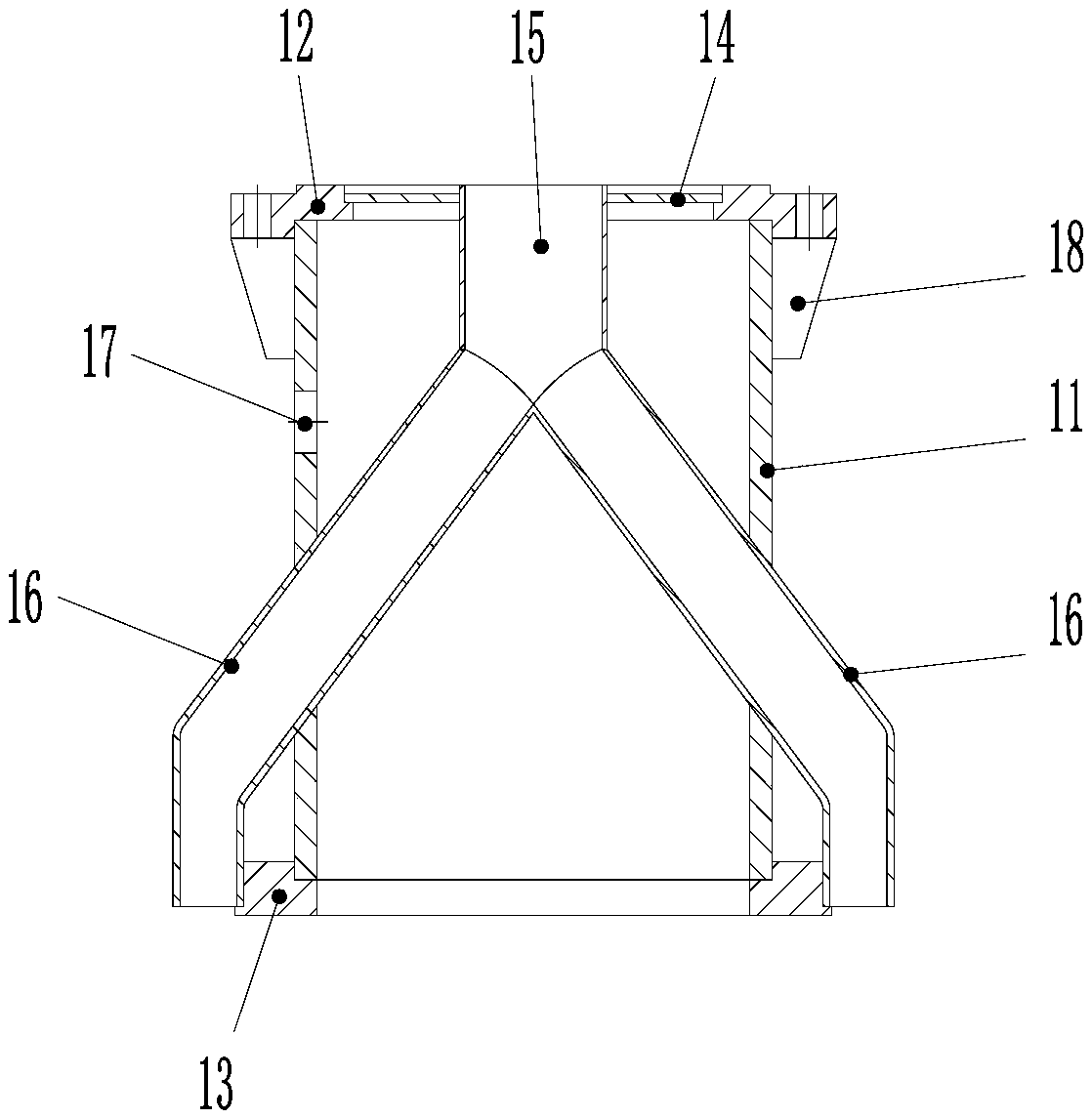
[0048] The drilling tool reducing device 10 is: composed of an annular outer pipe 11 , an upper flange 12 , a lower flange 13 , a blocking plate 14 , a main conveying pipe 15 , two auxiliary conveying pipes 16 and ribs 18 . The two ends of the annular outer pipe 11 are respectively provided with an upper flange 12 and a lower flange 13. The blocking plate 14 is installed on the upper flange 12. One end of the main delivery pipe 15 in the outer pipe 11 is connected with the blocking plate 14, and the other end is connected with the two One end of two auxiliary delivery pipes 16 is connected to form a herringbone structure and communicates internally, and the other end of the two auxiliary delivery pipes 16 protrudes fr...

Embodiment 2

[0059] Embodiment 2 A kind of construction method of cast-in-place concrete pipe single pile pile

[0060] Such as Figure 12 and Figure 13 As shown, adopt the cast-in-place concrete pipe pile construction device of embodiment 1 to complete the cast-in-situ concrete squeezed soil pipe pile, the method is as follows:

[0061] 1. If Figure 12 In (a), level the site, assemble the cast-in-place concrete pipe pile construction device and supporting construction equipment, place the pile hole position line, align the pile driver drilling tool with the pile position, and adopt a long auger drilled pile frame 60 with a large torque. The power head device 40 is installed on the frame 60, and the power head device 40 is used in conjunction with the concrete delivery pump. The drilling tool reducing device 10, several standard section drilling tools 20 and the bottom section drilling tool 30 are installed in sequence under the power head device 40.

[0062] 2. If Figure 12In (b), ...

Embodiment 3

[0065] Example 3 A construction method of cast-in-situ concrete pipe pile occlusal pile

[0066] Using the cast-in-place concrete pipe pile construction device of Embodiment 1, the difference is that the spiral extruding blade I23 on the outer wall of the core pipe I22 of the standard section drilling tool 20 is replaced by a spiral blade 37, and the core pipe II32 of the bottom section drilling tool 30 The screw extruding soil blade II36 on the outer wall of the screw rod part is replaced by a screw blade 37.

[0067] Such as Figure 12 and Figure 14 As shown, to complete the cast-in-place concrete pipe pile occlusal pile, the method is as follows:

[0068] 1, with the step 1 of embodiment 2;

[0069] 2, with the step 2 of embodiment 2;

[0070] 3, with the step 3 of embodiment 2, finish first cast-in-place plain concrete pipe 53 pile constructions;

[0071] 4. Move the cast-in-place concrete pipe pile construction device and supporting construction equipment to move th...


PUM

PropertyMeasurementUnit
Heightaaaaaaaaaa

Abstract

The invention relates to a construction device of a cast-in-place concrete pipe pile and a construction method of a formed pile. The construction device comprises a drilling tool reducing device, a plurality of standard drilling tools and a bottom drilling tool, wherein on the drilling tool reducing device, a main conveying pipe in an outer pipe is connected with one end of two secondary conveyingpipes so as to form a Y-shaped structure, the interiors communicate with each other, and the other ends of the two secondary conveying pipes protrude from the outer pipe and are symmetrically and fixedly arranged at the outer edge of a lower flange; on the standard drilling tools, two concrete filling pipes I are symmetrically fixed to the outer wall of a core pipe I; on the bottom drilling tool,two concrete filling pipes II are symmetrically fixed to the outer wall of a core pipe II, and door blocking devices which can be opened and closed are respectively arranged on the lower ends of thetwo concrete filling pipes II; the drilling tool reducing device, the plurality of standard drilling tools and the bottom drilling tool are connected in sequence; and the main conveying pipe, the secondary conveying pipes, the concrete filling pipes I and the concrete filling pipes II are connected together and communicate with each other. The construction device has the advantages of low construction cost, high pile bearing capability, high construction controllability, good quality and wide geologic adaptation.

Description

technical field [0001] The invention relates to the field of construction pile construction, in particular to a construction device for cast-in-place concrete pipe piles and a construction method for forming piles. Background technique [0002] In the existing construction pile foundation design, the cast-in-place concrete piles are mostly cylindrical solid piles, and the calculation of pile bearing capacity is mainly based on vertical and horizontal bearing capacity. When the strength of the pile body meets the requirements, the pile The vertical bearing capacity of the pile is composed of side friction and end resistance around the pile, and the horizontal bearing capacity of the pile is determined by the geometric parameters of the cross section of the pile body. In order to increase the bearing capacity of a single pile, it is usually achieved by increasing the diameter of the pile and lengthening the pile body, which increases the amount of concrete poured into the pile...

Claims


Application Information

Patent Timeline
IPC IPC(8): E02D5/34E02D5/36E21B7/00E21B17/22
CPCE21B7/00E21B17/22E02D5/34E02D5/36
Inventor 刘守进张喜才赵世范李殊睿刘帅夏日光
Owner 刘守进
Learn More