Positioning structure for integrated clamp shell and mounting support in car welding clamp

A welding fixture and mounting support technology, which is applied in welding equipment, auxiliary welding equipment, welding/cutting auxiliary equipment, etc., can solve the problems of insufficient compactness of automobile welding design, complex positioning structure design, and insufficient convenience of positioning and coordination, etc., to achieve The application effect is remarkable, it is convenient for maintenance, replacement and assembly of the cylinder, and the product design is compact and reasonable.

Pending Publication Date: 2019-01-11
TIANJIN FUZHEN IND EQUIP
View PDF0 Cites 0 Cited by
  • Summary
  • Abstract
  • Description
  • Claims
  • Application Information

AI Technical Summary

Problems solved by technology

[0002] At present, in the environment of global economic integration, in order to adapt to market demand and meet customer requirements, companies will use European or American standards for the design and manufacture of automotive welding equipment; There is only one type of clamp in the market, that is, there are only screw holes, pin holes and positioning surfaces on the cylinder shell, and the installation of the cylinder must be installed from the support end to the cylinder. The problem of disassembly and assembly of bolts needs to be considered during design, so the support is bulky, the design of automobile welding is not compact enough, the design of positioning structure is complicated, and the positioning and coordination are not simple enough

Method used


Image

  • Positioning structure for integrated clamp shell and mounting support in car welding clamp
  • Positioning structure for integrated clamp shell and mounting support in car welding clamp
  • Positioning structure for integrated clamp shell and mounting support in car welding clamp

Examples


Embodiment Construction

[0024] Below in conjunction with the accompanying drawings and preferred embodiments, the specific implementation, structure and features provided by the present invention are described in detail as follows:

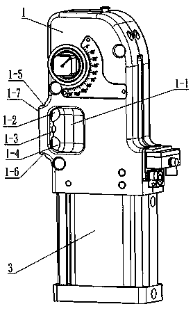
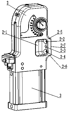
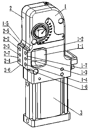
[0025] Such as Figure 1-Figure 4 As shown, an integrated clamp housing and mounting support positioning structure in an automobile welding fixture, the clamp housing in this structure includes a left housing 1, a right housing 2 and a cylinder 3; and The clamp housing is positioned in cooperation with the mounting support 4 in the automobile welding fixture.

[0026] The left side of the left side housing 1 is provided with a left groove 1-1 on the left side, and the left side of the left side housing 1 is provided with a boss, and the boss is of the same height as the top of the left groove 1-1. The following is the same height as the bottom of the left groove 1-1, and the upper left positioning surface 1-5 is provided on the boss, which is a horizontal plane; the low...


PUM


Abstract

The invention relates to a positioning structure for an integrated clamp shell and a mounting support in a car welding clamp. The clamp shell in the positioning structure comprises a left side shell,a right side shell and an air cylinder. A left groove is formed in the left side of the front face of the left side shell, a boss is arranged on the left side face of the left side shell, and a firstcounterbore hole, a first pin hole and a second counterbore hole are formed in the boss in an evenly distributed mode from top to bottom; and an upper left positioning face is arranged on the boss, alower left positioning face is arranged on the lower side of the boss, and a left mounting face is arranged on the boss face. A right groove is formed in the right side of the front face of the rightside shell, a boss is arranged on the right side face of the right side shell, and a third counterbore hole, a second pin hole and a fourth counterbore hole are formed in the boss in an evenly distributed mode from top to bottom; and an upper right positioning face is arranged on the boss, a lower right positioning face is arranged on the lower side of the boss, and a right mounting face is arranged on the boss face. The clamp shell structure and the mounting support in the car welding clamp are positioned in a matched mode. The positioning structure is simple in structure, positioning, demounting and mounting are easy and convenient, the design efficiency is improved, and the application effect is quite significant.

Description

technical field [0001] The invention relates to an automobile welding fixture, in particular to a positioning structure of an integrated clamp housing and a mounting support in the automobile welding fixture. Background technique [0002] At present, in the environment of global economic integration, in order to adapt to market demand and meet customer requirements, companies will use European or American standards for the design and manufacture of automotive welding equipment; There is only one type of clamp in the market, that is, there are only screw holes, pin holes and positioning surfaces on the cylinder shell, and the installation of the cylinder must be installed from the support end to the cylinder. The problem of disassembly and assembly of bolts needs to be considered during design, so the support is bulky, the design of automobile welding is not compact enough, the design of positioning structure is complicated, and the positioning and coordination are not simple...

Claims


Application Information

Patent Timeline
IPC IPC(8): B23K37/04
CPCB23K37/0443
Inventor 董豪武小明李昊卢寿福赵锡茂
Owner TIANJIN FUZHEN IND EQUIP
Why Eureka
Try Eureka