A high parallelism installation method and camera of a large target surface sensor
An installation method and sensor technology, applied to color TV parts, TV system parts, TVs, etc., can solve the problems of excessive parallelism error between the lens and the sensor, unfavorable maintenance of camera parts, high cost of positioning tooling, etc., to achieve Effects that improve clarity, optimize effects, and improve accuracy
- Summary
- Abstract
- Description
- Claims
- Application Information
AI Technical Summary
Problems solved by technology
Method used
Image

Examples
Embodiment 1
[0026] The following will refer to Figure 1 to Figure 3 Embodiments of the present application will be described.
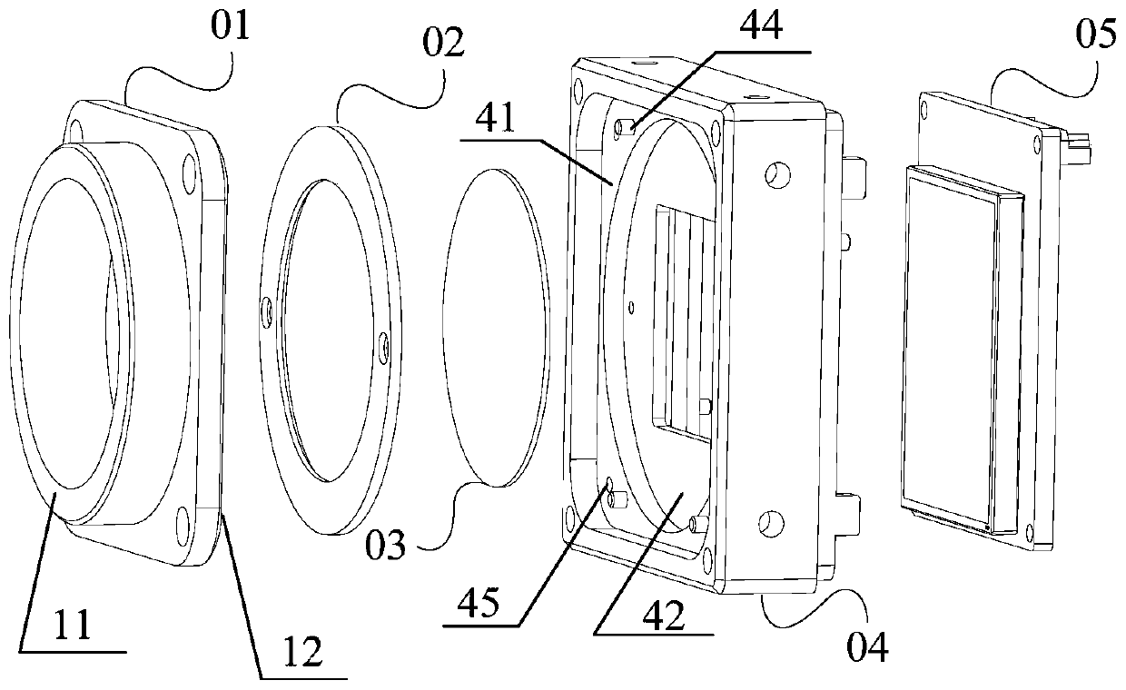
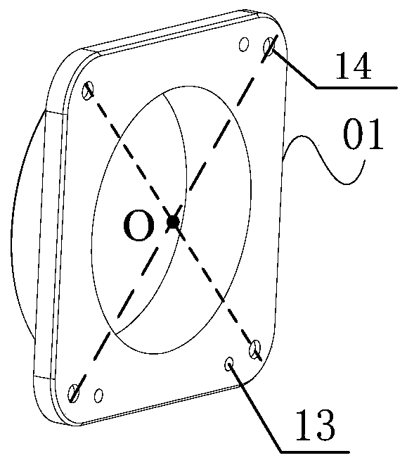
[0027] Such as figure 1 As shown, the first embodiment provides a camera, including: a front housing 04, an image sensor assembly 05 and a lens flange 01; the lens flange 01 is provided with a first plane 11, a second plane 12 and a first positioning hole 13 , the first plane 11 is set on the outside of the lens flange 01, the second plane 12 is set on the inside of the lens flange 01, and the first positioning hole 13 is set on the second plane 12;
[0028] Specifically, such as figure 2 As shown, in order to prevent relative displacement of the assembled lens flange 01 and front housing 04 during processing, a first positioning hole is provided on the second plane 12 of the lens flange 01 so as to align with the first positioning of the front housing 04 The column 44 performs the first positioning assembly, and by setting three first positioning holes, on ...
Embodiment 2
[0045] The following will refer to Figure 4 Embodiments of the present application will be described.
[0046] This embodiment 2 provides a high parallelism installation method for a large target surface sensor, which is suitable for installing the lens flange, front shell and image sensor assembly of the camera. In order to simplify the description of this embodiment 2, the Taking the camera as an example, the installation method includes the following steps:
[0047] Step 1, fix the front case 04 and the lens flange 01 on the processing platform 06 respectively, and process the parallelism of the front case 04 and the lens flange 01;
[0048] Wherein, the processing plane of the front housing 04 includes the third plane 41 and the fourth plane 42, the processing plane of the lens flange 01 includes the first plane 11 and the second plane 12, and the sensor mounting surface 43 of the front housing 04 is not processed for parallelism. , After the front shell 04 and the lens...
Embodiment 3
[0066] The following will refer to Figure 5 to Figure 6 Embodiments of the present application will be described.
[0067] The various components of the camera involved in this embodiment are the same as those in the first embodiment, and the installation method of the various components involved is the same as that in the second embodiment. In this embodiment, the image sensor assembly 05 is description, such as Figure 5 As shown, the image sensor assembly 05 involved in this embodiment includes: an image sensor circuit board 501 , an image sensor socket 502 , a heat dissipation plate 503 , a heat-conducting silicone pad 504 and an image sensor 505 .
[0068] The image sensor circuit board 501 can be a PCB board, with copper leakage areas arranged around it, and metallized mounting holes are respectively provided at the four corners, which can be used to fasten the image sensor circuit board 501 to the front cover 04, and the metallized mounting holes and While the bolts ...
PUM
 Abstract
Description
Claims
Application Information
 - R&D
- Intellectual Property
- Life Sciences
- Materials
- Tech Scout
- Unparalleled Data Quality
- Higher Quality Content
- 60% Fewer Hallucinations
Browse by: Latest US Patents, China's latest patents, Technical Efficacy Thesaurus, Application Domain, Technology Topic, Popular Technical Reports.
© 2025 PatSnap. All rights reserved.Legal|Privacy policy|Modern Slavery Act Transparency Statement|Sitemap|About US| Contact US: help@patsnap.com